Reflection mirror apparatus, exposure apparatus and device manufacturing method

a technology of reflection mirror and exposure apparatus, which is applied in the field of exposure apparatus, can solve the problems of affecting the image formation performance and illumination performance of the wafer, the inability to use the optical control system using an optical lens, and the inability to ensure the accuracy of the surface form of about 1 nm,

Inactive Publication Date: 2008-03-25
CANON KK
View PDF26 Cites 8 Cited by
  • Summary
  • Abstract
  • Description
  • Claims
  • Application Information

AI Technical Summary

Problems solved by technology

As the extreme ultraviolet light is greatly attenuated when it passes through an object, an optical control system using an optical lens cannot be employed.
Accordingly, as apparent from the above description, the extremely high accuracy of the surface form of about 1 nm cannot be ensured due to displacement of the mirror reflection surface by heat.
In the case of the projection optical system, the above degradation of the accuracy of the surface form in the mirror causes degradation of image formation performance and illumination on the wafer.
For example, in the case of the illumination system mirror, the degradation of accuracy of the surface form causes a reduction of illumination and degradation of illumination evenness in the exposure light to a mask.
Further, in the case of the optical source mirror, the degradation of the accuracy of the surface form causes degradation of illumination due to poor focusing of the light source.
Such degradation causes degradation of basic performance of the exposure apparatus such as degradation of exposure accuracy and throughput.

Method used


Image

  • Reflection mirror apparatus, exposure apparatus and device manufacturing method
  • Reflection mirror apparatus, exposure apparatus and device manufacturing method
  • Reflection mirror apparatus, exposure apparatus and device manufacturing method

Examples


first embodiment

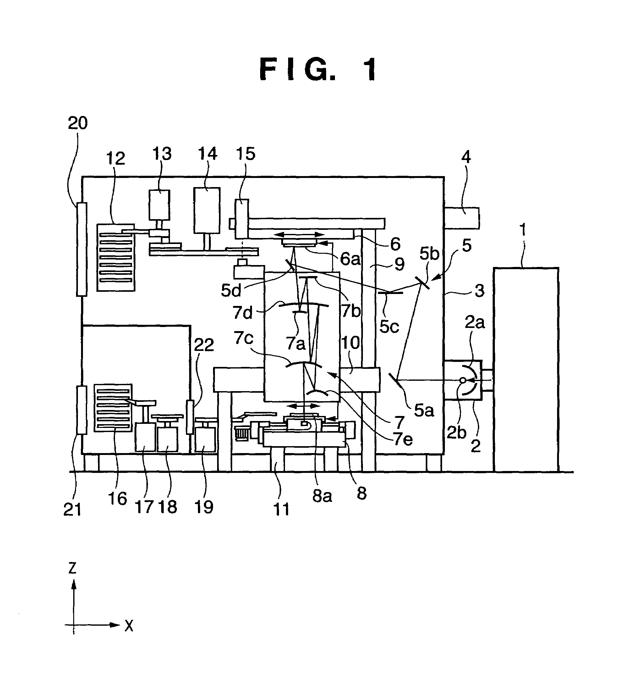
[0026]FIG. 1 is a schematic cross-sectional view showing the structure of an exposure apparatus according to a first embodiment of the present invention. In FIG. 1, reference numeral 1 denotes an excitation laser. The laser is emitted toward a point where a light source material is gasified, liquefied or spray-gasified, as a light emission point of light source, for plasma excitation of atoms of the light source material, thereby emitting extreme ultraviolet light. In the present embodiment, a YAG solid laser or the like is used as the excitation laser.

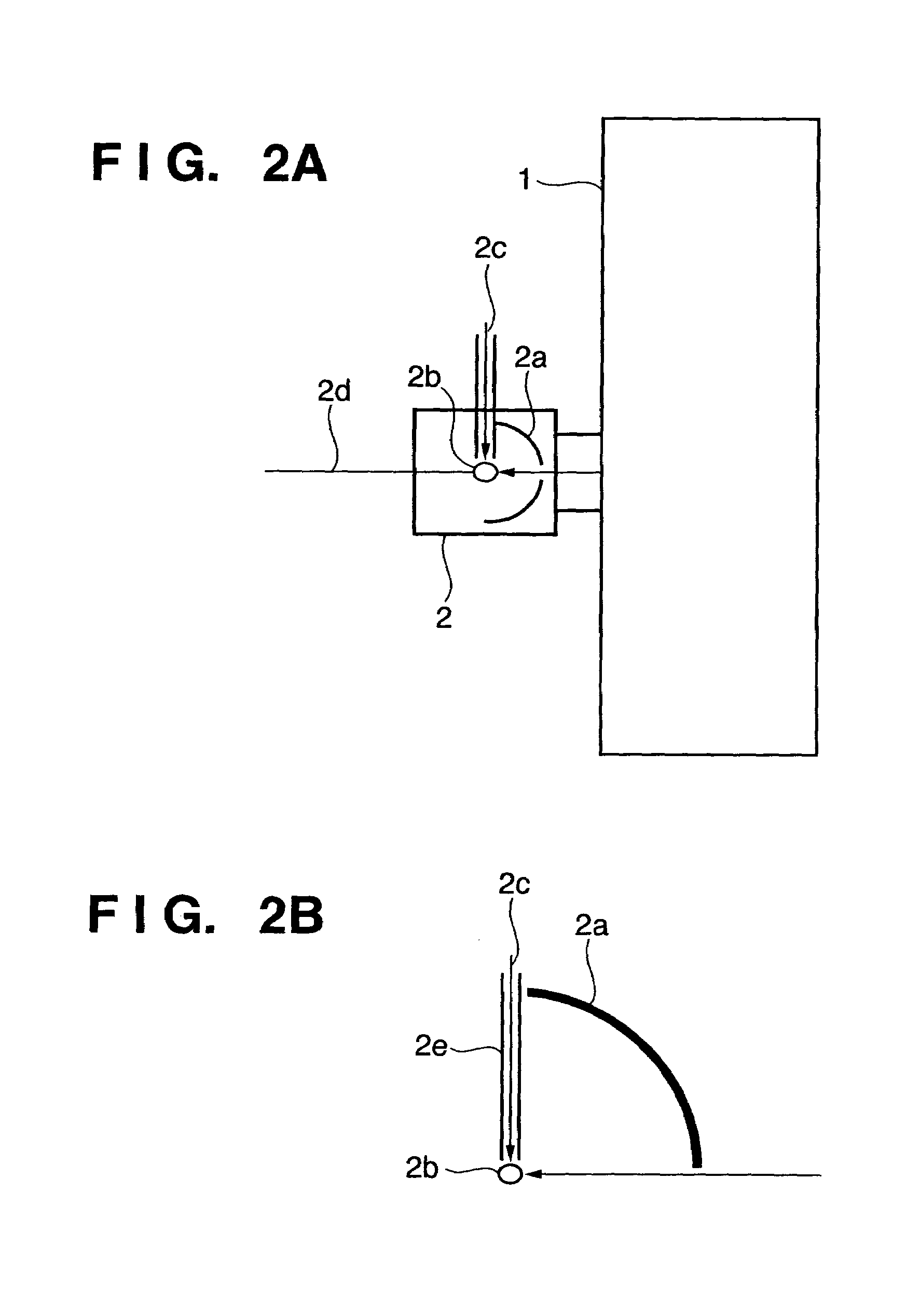
[0027]Numeral 2 denotes a light source unit having a structure in which a vacuum status is maintained. FIGS. 2A and 2B show the internal structure of the light source unit 2. Numeral 2b denotes a light source indicating an actual light emission point of exposure light source. Numeral 2a denotes a light source mirror which gathers all the light from the light source 2b and reflects the light in a light emission direction, thus generati...

second embodiment

[0055]FIG. 6 shows the cooling mechanism according to a second embodiment of the present invention. In FIG. 6, constituent elements corresponding to those in the first embodiment (FIG. 3B) have the same reference numerals. In the first embodiment, plural separate radiation plates are provided for the exposure light reflection surface and the rear surface of the mirror, and respectively optimized temperature-control cooling media are passed through the respective radiation plates. In the second embodiment, as shown in FIG. 6, radiation plates 125a and 125b are simply separated for the exposure light reflection surface and the rear surface of the mirror 30. Note that the radiation plate 125a is provided with an opening (not shown) to ensure a passage area for the exposure light 2d incoming and outgoing to / from the reflection surface of the mirror 30. Further, the cooling mechanism having this form is preferably used in a portion where the amount of exposure light incident on the mirro...

third embodiment

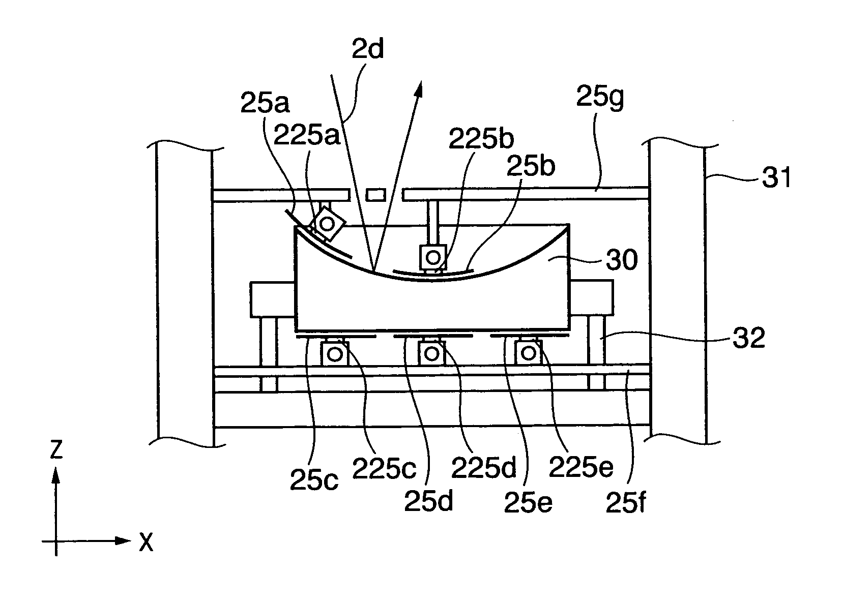
[0058]FIG. 7 shows the cooling mechanism according to a third embodiment of the present invention. In FIG. 7, constituent elements corresponding to those in the first embodiment (FIG. 3B) have the same reference numerals. In the first embodiment, the cooling pipes are directly connected to the radiation plates so as to directly cool the radiation plates. In the third embodiment, Peltier elements 225a to 225e as solid heat-transfer elements are provided between the radiation plates 25a to 25e and the cooling pipes 23a to 23e. As shown in FIG. 7, it may be arranged such that the temperature control of the radiation plates is performed by the Peltier elements, and temperature rising portions in heat radiation portions on the rear surfaces of the Peltier elements are cooled by the cooling media in the cooling pipes.


PUM

PropertyMeasurementUnit
wavelengthaaaaaaaaaa
reflectivityaaaaaaaaaa
temperatureaaaaaaaaaa

Abstract

A reflection mirror apparatus, used in a reflection optical system of an exposure apparatus which performs exposure processing by guiding exposure light by reflection, has a mirror having a reflection surface to reflect the exposure light, and radiation plates for radiation-cooling provided in positions away from an outer surface of the mirror. The radiation plates are provided so as to ensure a passage area for the exposure light incident on and reflected from the reflection surface of the mirror. Further, the respective radiation plates are temperature-controlled by cooling liquid flowing through cooling pipes. Thus the temperature rise of the mirror used in the reflection optical system of the exposure apparatus can be suppressed, and the accuracy of surface form of the mirror reflection surface can be maintained.

Description

TECHNICAL FIELD[0001]The present invention relates to an exposure apparatus used in a semiconductor manufacturing process, and more particularly, to an exposure apparatus with extreme ultraviolet light as an exposure light source and a reflection mirror apparatus used in a reflection optical system of the exposure apparatus.BACKGROUND ART[0002]As a projection exposure apparatus in which a reticle pattern is projected and transferred on a silicon wafer, an apparatus using extreme ultraviolet (EUV) light having a wavelength of 13 to 14 nm as an exposure light source has been proposed. As the extreme ultraviolet light is greatly attenuated when it passes through an object, an optical control system using an optical lens cannot be employed. Accordingly, in the above exposure apparatus using the extreme ultraviolet light as an exposure light source, the exposure light is controlled by plural mirrors provided in a vacuum space (reflection optical system).[0003]The reflection optical syste...

Claims


Application Information

Patent Timeline
Patent Type & Authority Patents(United States)
IPC IPC(8): G03B27/52G02B7/195G03B27/42G03B27/54G02B5/10G02B17/00G03F7/20G21K1/06H01L21/027
CPCG02B7/1815G03F7/70175G03F7/702G03F7/70891G21K1/06G03F7/70233G21K2201/067G21K2201/065G03F7/2041
Inventor MIYAJIMA, YOSHIKAZU
Owner CANON KK
Why Eureka
Try Eureka