Fluorescence measurement apparatus
a fluorescence measurement and apparatus technology, applied in the direction of luminescent dosimeters, optical radiation measurement, instruments, etc., can solve the problems of increasing the s/n ratio of measurement, affecting the detection sensitivity, and prone to autofluorescence, so as to achieve high sensitivity, increase fluorescence, and high measurement accuracy
- Summary
- Abstract
- Description
- Claims
- Application Information
AI Technical Summary
Benefits of technology
Problems solved by technology
Method used
Image
Examples
embodiment 1
[0048]Hereinafter, a fluorescence measurement apparatus according to a first embodiment of the present invention will be described with reference to the drawings.
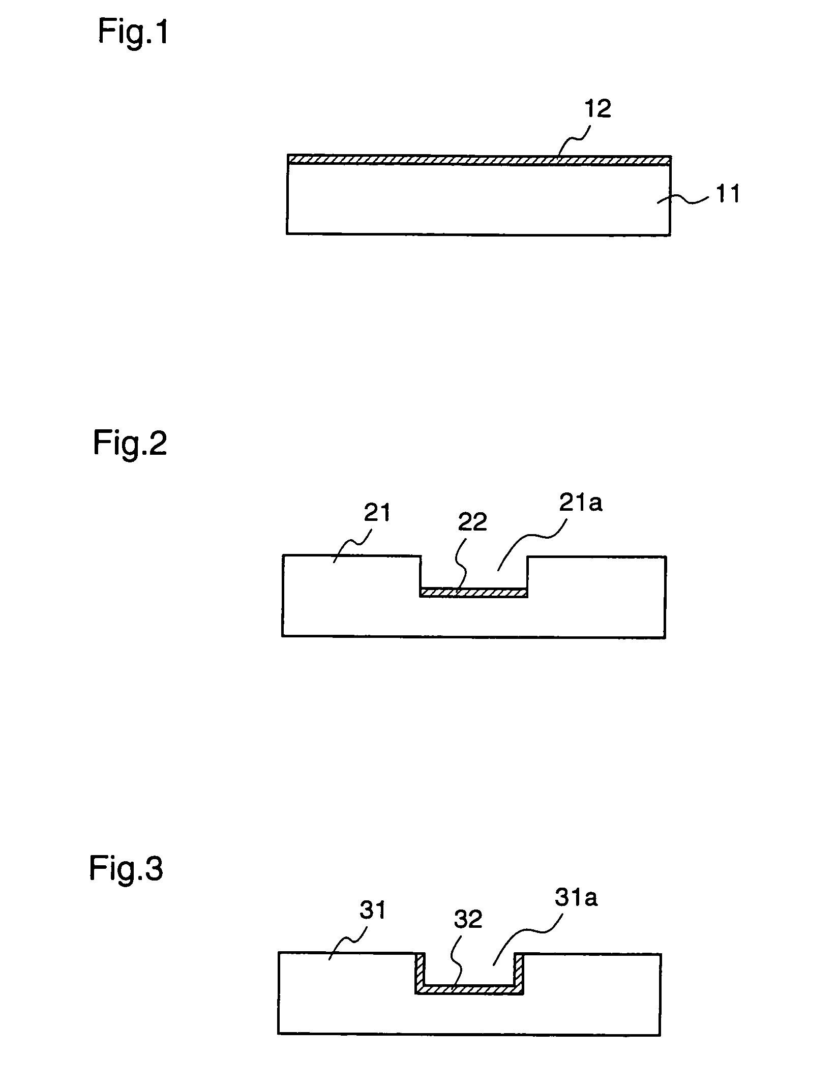
[0049]Initially, the construction of a substrate according to the first embodiment will be described with reference to FIGS. 1˜3. In this first embodiment, a “substrate” means any of a substrate, a cell, and a channel on which a sample is disposed.
[0050]FIGS. 1˜3 are end views illustrating examples of substrates according to the first embodiment. FIG. 1 shows a flat-plate-shaped substrate, and FIGS. 2 and 3 show substrates on which concave wells or channels are formed, respectively.
[0051]As shown in the figures, the substrates 11, 21, and 31 according to the first embodiment are provided with wavelength selection means 12, 22, and 32, respectively, for reflecting excitation light, and transmitting fluorescence that is emitted from samples disposed on the respective substrates. The wavelength selection means 12, 22, and 32 a...
example 1
[0076]Hereinafter, an example of a fluorescence measurement apparatus will be described with reference to FIG. 7. The fluorescence measurement apparatus of the present invention is not restricted to the construction described hereinafter.
(1) Fabrication of Substrate
[0077]A substrate 61 comprising a high-transparency polymethylmethacrylate, in which a concave channel 61a having a width of 80˜120 μm and a depth of 30˜70 μm is formed at the surface, is prepared, and a dielectric multilayer 62 is coated at the bottom surface of the channel 61a.
[0078]The dielectric multilayer 62 has a construction in which a high refractive index layer A (titanium dioxide, refractive index 2.4) and a low refractive index layer B (silicon dioxide, refractive index 1.5) are alternately deposited. Both the high refractive index layer A and the low refractive index layer B are deposited by reactive sputtering.
[0079]Hereinafter, film depositing conditions by reactive sputtering used in this example will be d...
example 2
[0085]Hereinafter, another example of a fluorescence measurement apparatus will be described with reference to FIG. 9. The fluorescence measurement apparatus of the present invention is not restricted to the construction described hereinafter.
(1) Fabrication of Substrate
[0086]A substrate 61 on which a dielectric multilayer 62 is deposited, which is used in this second example, is fabricated in the same method as that described for the first example.
(2) Placement of Top Plate
[0087]In this second example, a top plate 91 having, on its one surface, deposition of a reflection layer 92 that reflects the excitation light emitted from the excitation light source 63, is disposed on the concave channel 61a formed in the substrate 61 so that the reflection layer 92 faces the substrate 61. At this time, the top plate 91 is disposed on the substrate 61 so as not to entirely cover the opening of the channel 61a that is formed in the substrate 61, i.e., the top plate 91 is disposed so as to secur...
PUM
 Abstract
Description
Claims
Application Information
 - R&D
- Intellectual Property
- Life Sciences
- Materials
- Tech Scout
- Unparalleled Data Quality
- Higher Quality Content
- 60% Fewer Hallucinations
Browse by: Latest US Patents, China's latest patents, Technical Efficacy Thesaurus, Application Domain, Technology Topic, Popular Technical Reports.
© 2025 PatSnap. All rights reserved.Legal|Privacy policy|Modern Slavery Act Transparency Statement|Sitemap|About US| Contact US: help@patsnap.com


