
Single-sided NMR sensor with microscopic depth resolution

a single-sided, depth resolution technology, applied in the field of single-sided magnetic resonance imaging (mri) sensors, can solve the problems of poor depth resolution reported with single-sided sensors, complicated and expensive magnet geometries, and poor spatial resolution, so as to improve the flatness of the defined sensitive region, improve the flatness of the constant field slice, and improve the effect of magnetic field distribution

Active Publication Date: 2008-04-15
RWTH AACHEN UNIV
View PDF38 Cites 22 Cited by
  • Summary
  • Abstract
  • Description
  • Claims
  • Application Information

AI Technical Summary

Benefits of technology

The invention provides a handheld sensor and method for ex situ magnetic resonance profiling with microscopic resolution. The sensor includes a magnet system for producing a magnetic field constant in a plane external to the body. The sensor can be used for in situ microscopic profiling of samples unrestricted in size, with profiles having a resolution of about 25 μm. The scanning procedure based on the retuning of the transmitter frequency has been discovered to adopt robust methods that involve the mechanical repositioning of either the sample or the sensor. The invention makes it possible to obtain the performance of the STRAFI method with a low-cost open NMR sensor.

Problems solved by technology

Although the procedure is similar to the high-resolution stray field imaging technique (STRAFI), the depth resolution reported with single-sided sensors is rather poor.
Several attempts have been made to improve the flatness of the sensitive volume by tailoring the magnet geometry, but a space resolution hardly better than half a millimeter has been reported.
As a result of optimization procedures, where the field profile is improved playing with the position and orientation of a large number of permanent block magnets, complicated and expensive magnet geometries are obtained.
Nevertheless, there are strong deficiencies in this approach when the density profile is contrasted by the relaxation times or by the self-diffusion coefficient in order to improve the discrimination of heterogeneities.
It is well known that the spin lattice relaxation time T1 depends on the frequency, so that this type of contrast is not accessible for this scanning procedure.
Therefore, a systematic error in the measurement of T2eff due to the variation of B0 and B1 distribution with the depth is produced.
Finally, when contrast by diffusion is required, an unwanted dependence of the profile intensity is obtained due to the change of gradient intensity with the depth.

Method used


Image

  • Single-sided NMR sensor with microscopic depth resolution
  • Single-sided NMR sensor with microscopic depth resolution
  • Single-sided NMR sensor with microscopic depth resolution

Examples


Embodiment Construction

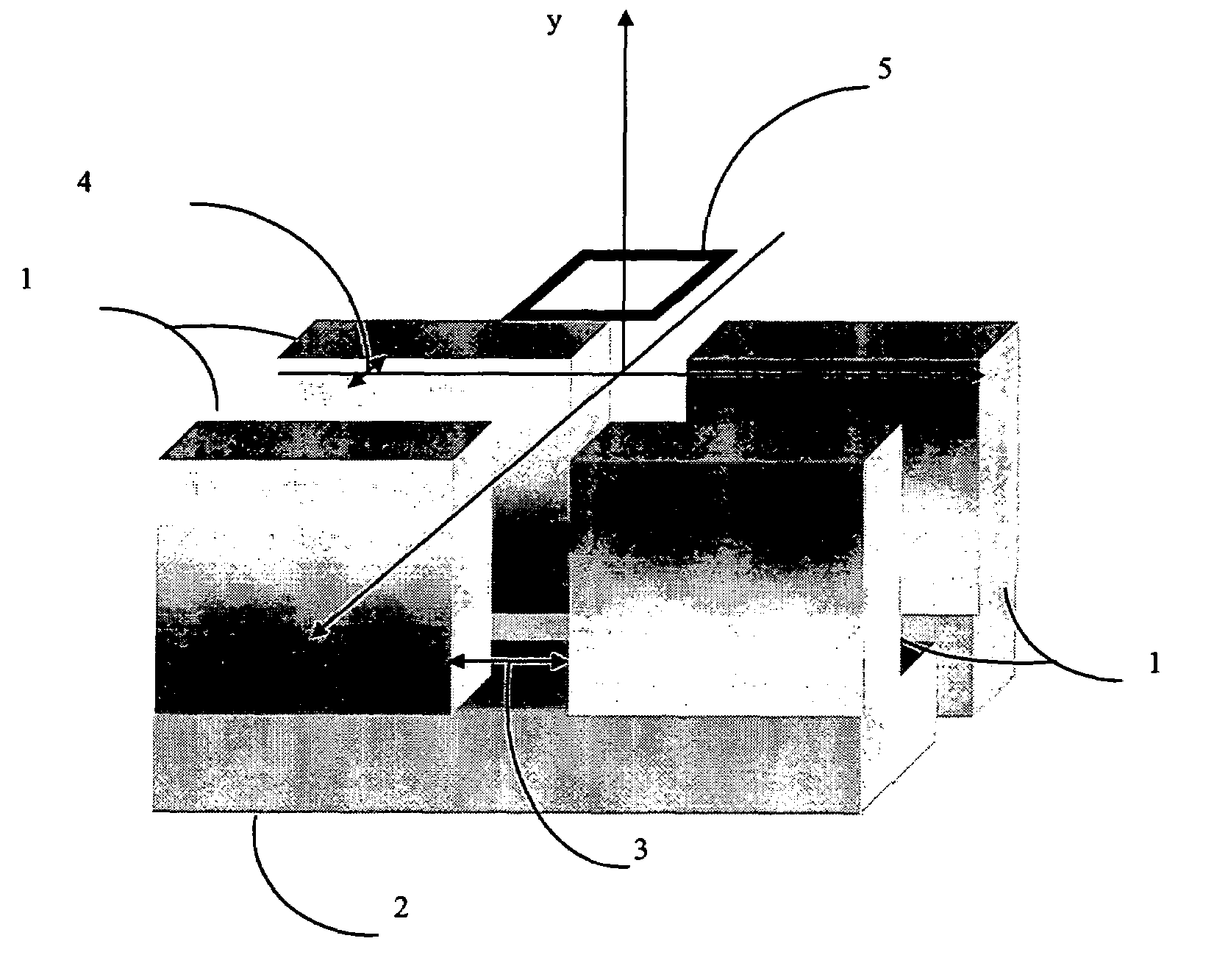
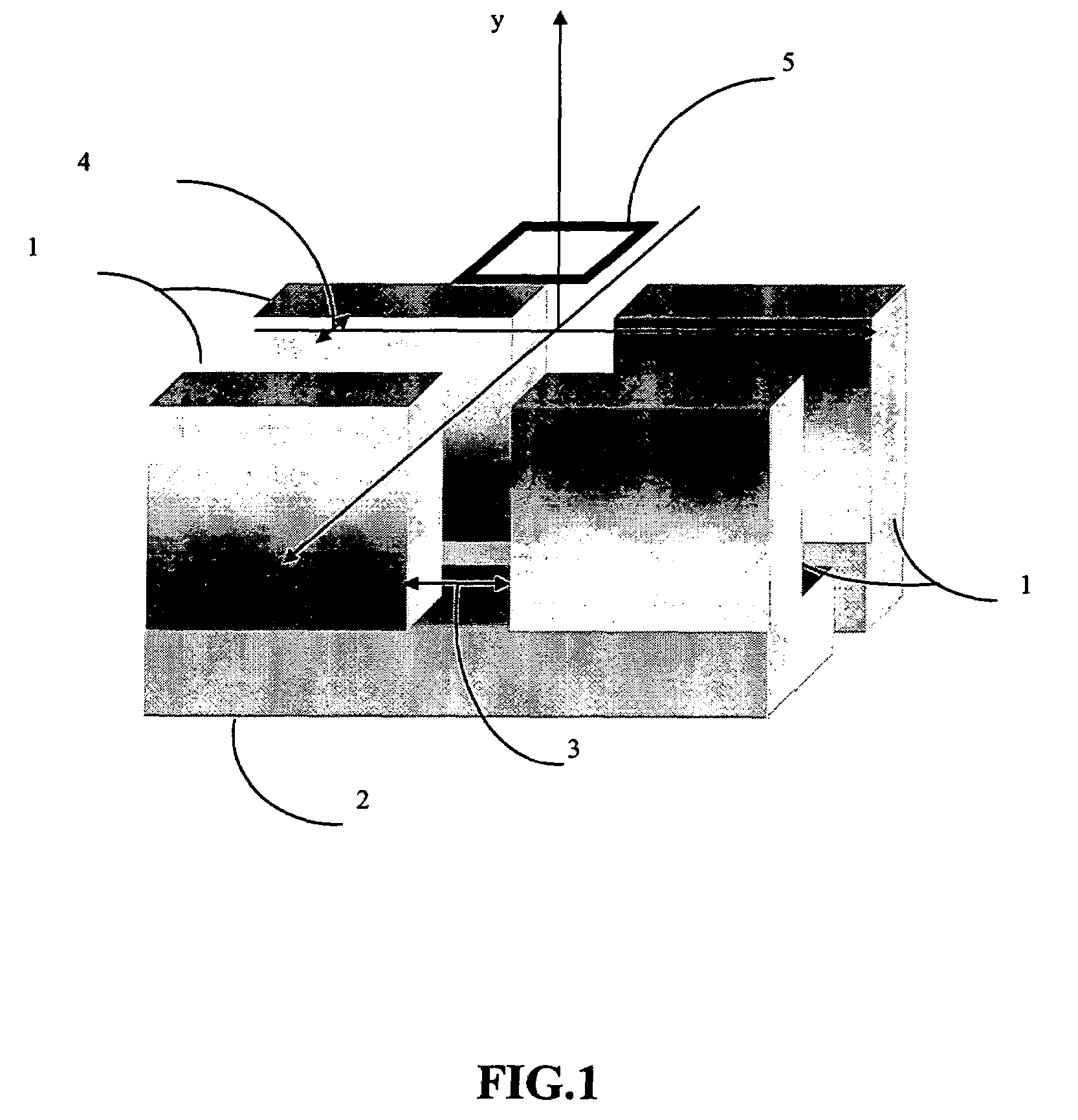
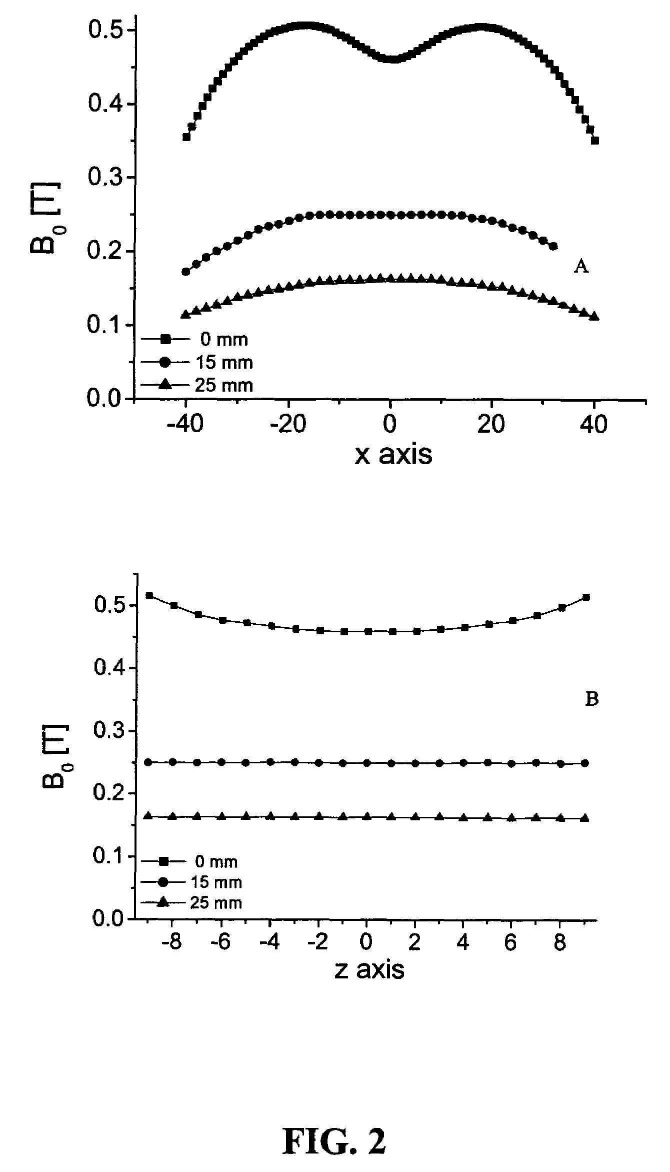
[0020]Turning to FIG. 1, the construction of a sensor prototype is presented. The magnets 1 are neodymium-iron-boron (NeFeB) blocks of 40, 50, and 45 mm along x, y and z, the gaps 3 and 4 are Gb=19 mm and Gs=4 mm respectively, and the iron yoke 2 is 20 mm thick. The magnetic field was measured using a Lakeshore Hall probe, and its spatial dependence along the two lateral directions is shown at three different depths in FIG. 2. While the behavior of the field along z is quadratic at the surface and become flat for larger depths, the field along x becomes flat at a depth of 15 mm away from the magnet, a distance that depends on the Gs chosen. The magnetic field at 15 mm from the surface and in the center of the device has a value of about 0.25 T along z, and has a strong uniform gradient of 11.2 T / m along the depth direction. At this depth, the device defines a plane of constant field intensity parallel to the surface with a field variation smaller than 0.1 mT in a region of 20 mm alo...


PUM


Abstract

A low-cost single-sided NMR sensor to produce depth profiles with microscopic spatial resolution is presented. The open geometry of the NMR sensor provides a non-invasive and non-destructive testing method to characterize the depth structure of objects of arbitrary size. The permanent magnet geometry generates one plane of constant magnetic field intensity parallel to the scanner surface. By combining the highly uniform static gradient with selective RF excitation, a thin flat sensitive slice can be defined. By moving the relative position between the slice and the object, one-dimensional profiles of the near surface of large samples are produced with high spatial resolution.

Description

BACKGROUND OF THE INVENTION[0001]1. Field of the Invention[0002]The present invention relates generally to the field of magnetic resonance, specifically to a single-sided magnetic resonance imaging (MRI) sensor that provides microscopic depth resolution.[0003]2. The Prior Art[0004]Single-sided nuclear magnetic resonance (NMR) sensors are used to characterize large size objects by measuring signal intensity, relaxation times and self-diffusion coefficients inside a sensitive volume generated in the sample by an open magnet. G. Eidmann, R. Savelsberg, P. Blümler and B. Blümich. The NMR-MOUSE, A Mobile Universal Surface Explorer, J. Magn. Reson. A122, 104-109 (1996). Two different magnet philosophies can be distinguished in previous works. One is described in the U.S. Pat. No. 6,489,872 by Fukushima and references included there, where a region of a homogeneous field is generated outside the magnet. The second type is described in G. Eidmann, R. Savelsberg, P. Blümler and B. Blümich, T...

Claims


Application Information

Patent Timeline
Patent Type & Authority Patents(United States)
IPC IPC(8): G01V3/00
CPCG01R33/3808G01R33/383
Inventor BLUMICH, BERNHARDCASANOVA, FEDERICOPERLO, JUAN
Owner RWTH AACHEN UNIV
Learn More