Nanostructured soldered or brazed joints made with reactive multilayer foils

a multi-layer foil and soldering technology, applied in the direction of exothermal chemical reactions for heating, printed circuit assembling, non-electric welding apparatus, etc., can solve the problems of weakened mechanical properties, slow cooling of braze or solder, joint enlarged microstructure, etc., to slow down cooling, weakened mechanical properties, and enlarged microstructure

Inactive Publication Date: 2008-04-22
THE JOHN HOPKINS UNIV SCHOOL OF MEDICINE
View PDF38 Cites 56 Cited by
  • Summary
  • Abstract
  • Description
  • Claims
  • Application Information

AI Technical Summary

Benefits of technology

[0007]The present inventors have determined that the conventional approach of brazing or soldering using furnaces or torches inherently produces sub-optimal joints. The furnace or torch heats not only the joint area but also the bodies to be joined. The heating of these bodies adjacent the joint area, combined with the insulating effect of the bodies, slows the cooling of the braze or solder and produces a joint of enlarged microstructure and weakened mechanical properties.
[0008]In accordance with the invention, bodies of materials are joined between mating surfaces by disposing reactive nanostructured foils between the mating surfaces and adjacent one or more layers of braze or solder. The composition and thickness of the foils are chosen, as by thermal modeling techniques, to minimize deleterious heating of the bodies and to provide an optimal heat profile to produce a nanostructured joint having superior mechanical properties.

Problems solved by technology

The heating of these bodies adjacent the joint area, combined with the insulating effect of the bodies, slows the cooling of the braze or solder and produces a joint of enlarged microstructure and weakened mechanical properties.

Method used


Image

  • Nanostructured soldered or brazed joints made with reactive multilayer foils
  • Nanostructured soldered or brazed joints made with reactive multilayer foils
  • Nanostructured soldered or brazed joints made with reactive multilayer foils

Examples


Embodiment Construction

[0045]This description is divided into three parts. Part I describes and illustrates reactive foil joining and the resulting joints. Part II describes a thermal modeling technique useful optimizing reactive foil joining, and Part III exemplifies the application of the thermal model to produce superior joints. References indicated by bracketed numbers are fully cited in an attached List.

I. The Method And Resulting Joined Products

[0046]A. Multilayer Reactive Foils and Their Use in Forming Joints

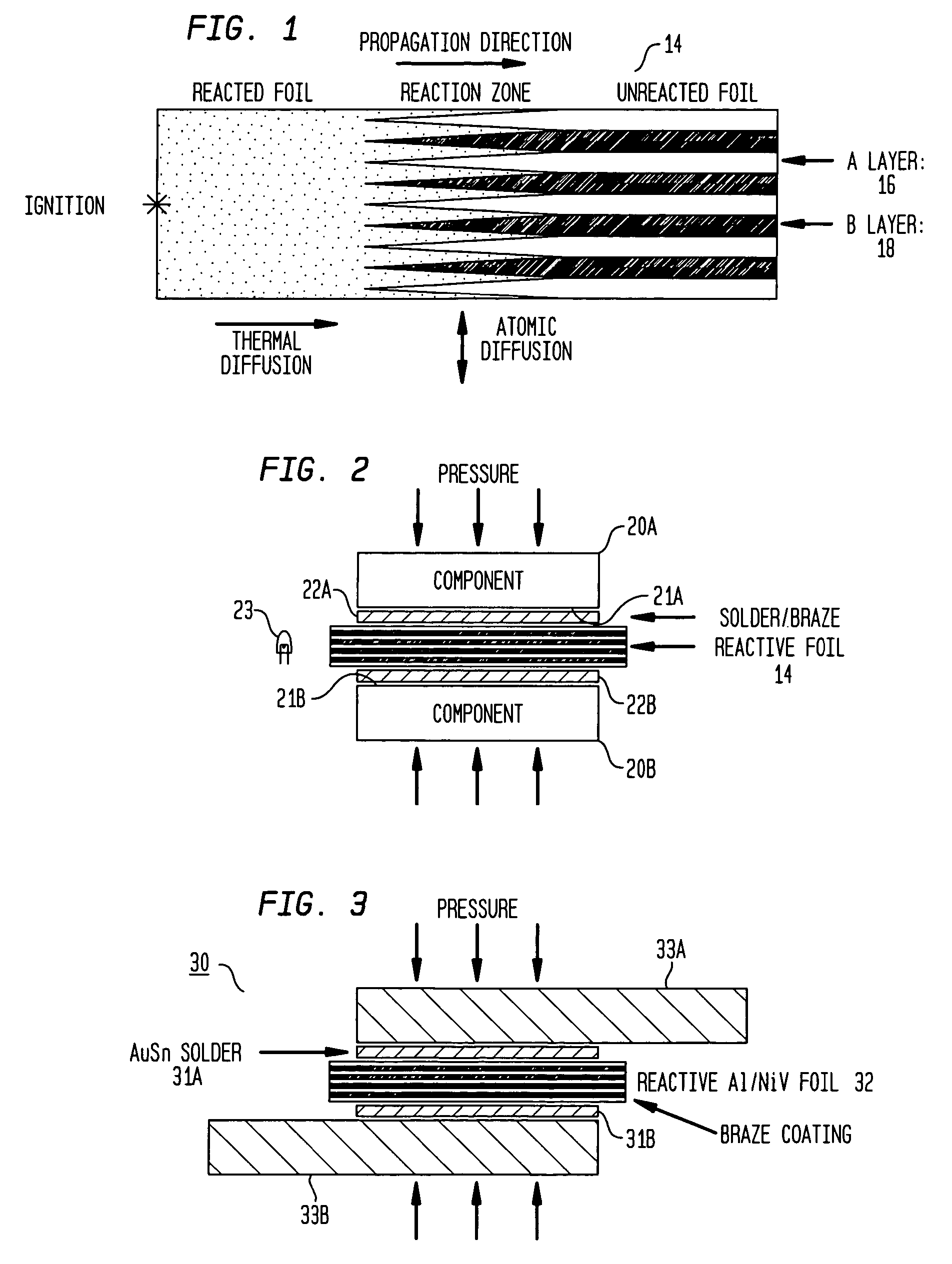
[0047]Self-propagating exothermic formation reactions have been observed in a variety of nanostructured multilayer foils, such as Al / Ni, Al / Ti, Ni / Si and Nb / Si foils [1-4]. These reactions are driven by a reduction in atomic bond energy. Once the reactions are initiated by a pulse of energy, such as a small spark or a flame, atomic diffusion occurs normal to the layering.

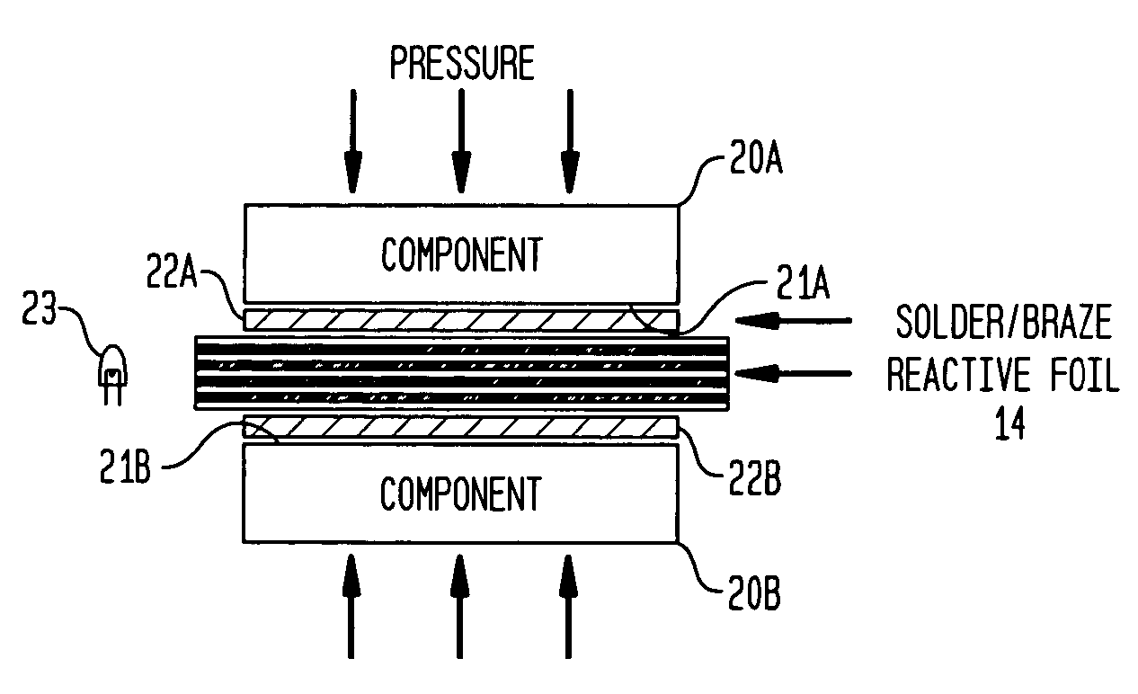
[0048]FIG. 1 schematically illustrates a multilayer reactive foil 14 made up of alternating layers 16 and 18 of materials A a...


PUM

PropertyMeasurementUnit
thickaaaaaaaaaa
pressureaaaaaaaaaa
temperatureaaaaaaaaaa

Abstract

Self-propagating formation reactions in nanostructured multilayer foils provide rapid bursts of heat at room temperature and therefore can act as local heat sources to melt solder or braze layers and join materials. This reactive joining method provides very localized heating to the components and rapid cooling across the joint. The rapid cooling results in a very fine microstructure of the solder or braze material. The scale of the fine microstructure of the solder or braze material is dependant on cooling rate of the reactive joints which varies with geometries and properties of the foils and components. The microstructure of the solder or braze layer of the joints formed by melting solder in a furnace is much coarser due to the slow cooling rate. Reactive joints with finer solder or braze microstructure show higher shear strength compared with those made by conventional furnace joining with much coarser solder or braze microstructure. It is expected that the reactive joints may also have better fatigue properties compared with conventional furnace joints.

Description

CROSS REFERENCE TO RELATED APPLICATIONS[0001]This application claims the benefit of U.S. Provisional Application Ser. No. 60 / 469,841 filed by Etienne Besnoin et al. on May 13, 2003 (entitled “Method of Controlling Thermal Waves In Reactive Multilayer Joining and Resulting Product”) and Ser. No. 60 / 475,830 filed by Jiaping Wang et al. on Jun. 4, 2003 (entitled “Microstructure of Solder or Braze in Joints Made With Freestanding Reactive Multilayer Foils”), both of which are incorporated herein by reference.[0002]This application is also a continuation-in-part of U.S. patent application Ser. No. 10 / 761,688 filed by T. Weihs et al. on Jan. 21, 2004 now abandoned (entitled “Freestanding Reactive Multilayer Foils”) which is a divisional of U.S. patent application Ser. No. 09 / 846,486 filed on May 1, 2001, now U.S. Pat. No. 6,736,942 (entitled “Freestanding Reactive Multilayer Foils”) which is a non-provisional application that claims the benefit of U.S. Provisional Application Ser. No. 60 / ...

Claims


Application Information

Patent Timeline
Patent Type & Authority Patents(United States)
IPC IPC(8): B23K1/00B23K31/02B32B15/01B32B5/00B23K20/00B23K20/06B23K20/08B23K28/00B23K31/12B23K35/02B23K35/34C06B21/00C06B45/14C23C14/14F24V30/00G05B17/02H05K3/34
CPCB23K1/0006B23K20/00B23K20/06B23K20/08B23K20/165B23K28/00B23K31/02B23K31/12B23K35/0238B23K35/34B32B15/01B32B15/017C06B21/0083C06B45/14C23C14/14F24J1/00G05B17/02H05K3/3494B23K1/0016Y10T428/12986B23K35/0233B23K2201/40B23K2203/04B23K2203/10H05K3/3463H05K2203/0405H05K2203/1163Y10T428/12493F24V30/00B23K2101/40B23K2103/05B23K2103/10
Inventor WANG, JIAPINGBESNOIN, ETIENNEKNIO, OMARWEIHS, TIMOTHY P.
Owner THE JOHN HOPKINS UNIV SCHOOL OF MEDICINE
Why Eureka
Try Eureka