
Method and apparatus for providing carrier synchronization in digital broadcast and interactive systems

Active Publication Date: 2008-05-06
DTVG LICENSING INC
View PDF13 Cites 29 Cited by
  • Summary
  • Abstract
  • Description
  • Claims
  • Application Information

AI Technical Summary

Benefits of technology

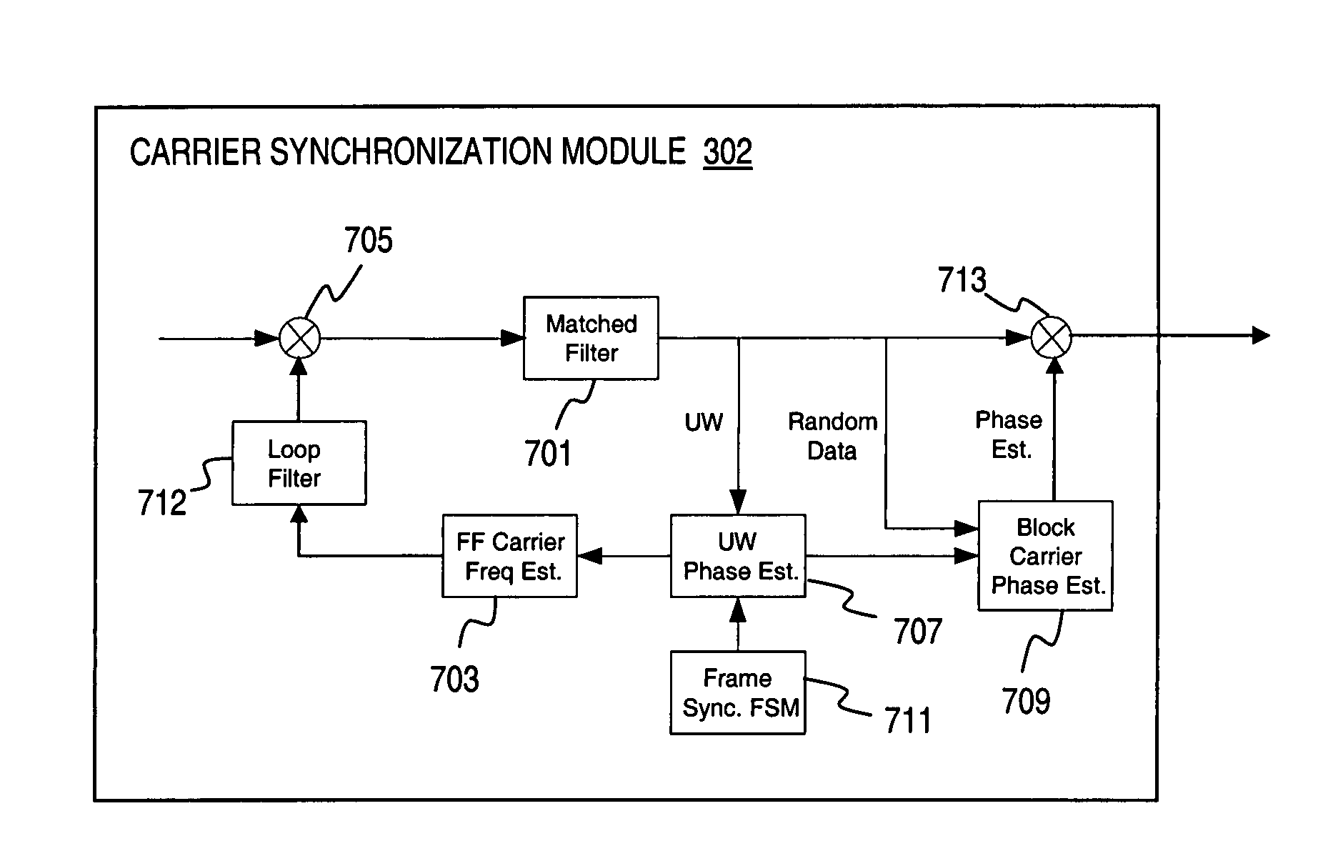
[0006]These and other needs are addressed by the present invention, wherein an approach for providing carrier synchronization in a digital broadcast and interactive system utilizing Low Density Parity Check (LDPC) codes and higher order modulation schemes. Unlike conventional continuous mode modems, the carrier synchronization method estimates carrier frequency and phase on a segment by segment basis, and continuously tracks carrier frequency between segments. The preamble of an FEC (Forward Error Correction) frame and optional pilot blocks (i.e., aggregated pilot symbols) which assist carrier synchronization, serve as the segment boundaries. In an exemplary embodiment, a physical layer frame includes a preamble, which can be used to assist with carrier synchronization, and an FEC codeword when no extra pilot symbols are needed. Alternatively, a pilot symbol insertion process divides the FEC codeword into multiple code segments, and inserts a pilot block in form of a unique word (UW) before each code segment of the physical layer frame. The preamble and optional pilot blocks serve as a training block. The carrier synchronization process utilizes the training block to estimate carrier frequency and phase, and reinitializes the phase tracking loop for each new segment. The frequency acquisition process involves computing an autocorrelation of a data-removed continuous wave (CW) signal. The carrier frequency of the received signal is estimated based on a weighted sum of the unwrapped phase of the accumulated autocorrelation values. With respect to frequency tracking, a feed-forward structure is implemented to generate estimates and to update the carrier frequency once per LDPC frame based on the phase estimates from the training block (i.e., preamble and / or UW). For phase tracking, a Two-Sweep Phase Locked Loop (PLL) architecture with a Maximum Likelihood (ML) phase detector is utilized. The Two-Sweep PLL tracks carrier phase on a segment by segment basis to estimate carrier phase based on both the past and future samples by sweeping the segment of data from both the forward and reverse directions. A segment can be a whole FEC codeword when no pilot blocks are present, or a code segment when pilot blocks are inserted. The above arrangement advantageously reduces the need to introduce additional overhead for carrier synchronization, drastically reduces the cycle slip rate and limits its error-propagating impact, and operates well in low Signal-to-Noise Ratio (SNR) environments, providing good immunity against thermal noise and phase noise. Additionally, the frequency estimation process provides a large frequency acquisition range and short acquisition time.

Problems solved by technology

Additionally, the frequency estimation process provides a large frequency acquisition range and short acquisition time.

Method used


Image

  • Method and apparatus for providing carrier synchronization in digital broadcast and interactive systems
  • Method and apparatus for providing carrier synchronization in digital broadcast and interactive systems
  • Method and apparatus for providing carrier synchronization in digital broadcast and interactive systems

Examples


Embodiment Construction

[0030]An apparatus, method, and software for efficiently providing carrier synchronization in a digital broadcast and interactive system are described. In the following description, for the purposes of explanation, numerous specific details are set forth in order to provide a thorough understanding of the present invention. It is apparent, however, to one skilled in the art that the present invention may be practiced without these specific details or with an equivalent arrangement. In other instances, well-known structures and devices are shown in block diagram form in order to avoid unnecessarily obscuring the present invention.

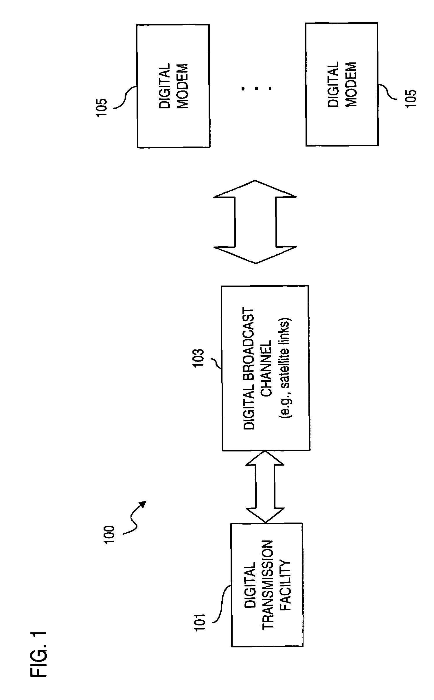
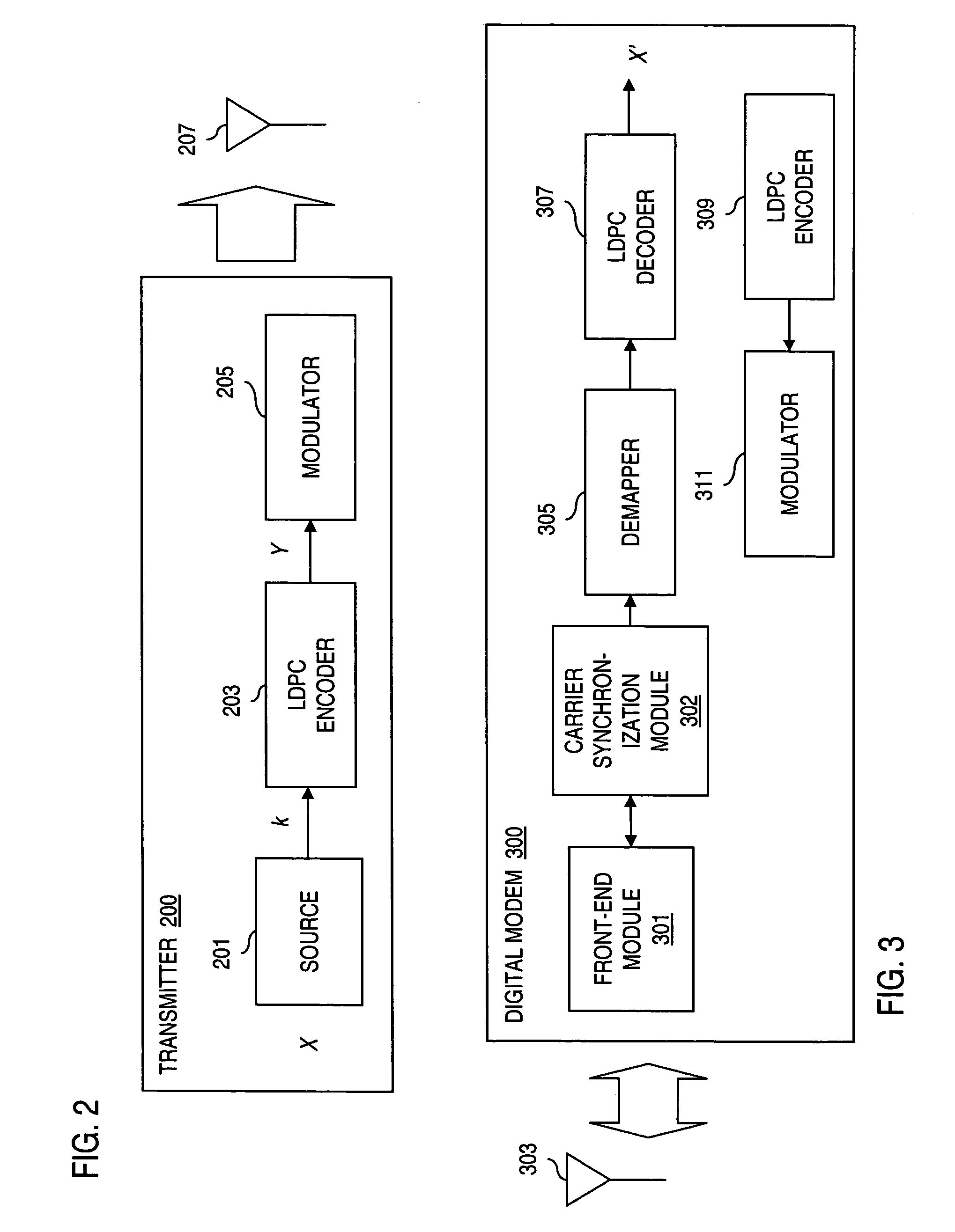
[0031]FIG. 1 is a diagram of a digital broadcast system configured to utilize Low Density Parity Check (LDPC) codes, according to an embodiment of the present invention. The digital communications system 100 includes a digital transmission facility 101 that generates signal waveforms for broadcast across a communication channel 103 to one or more digital mod...


PUM


Abstract

An approach is provided for supporting carrier synchronization in a digital broadcast and interactive system. A carrier synchronization module receives one or more signals representing a frame that includes one or more overhead fields (e.g., preamble and optional pilot blocks and one or multiple segments separated by pilot blocks). The module estimates carrier frequency and phase on a segment by segment basis and tracks frequency between segments. Carrier phase of the signal is estimated based upon the overhead field. Estimates carrier phase of random data field are determined based upon the estimated phase values from the overhead fields, and upon both the past and future data signals. Further, the frequency of the signal is estimated based upon the overhead fields and / or the random data field. The above arrangement is particularly suited to a digital satellite broadcast and interactive system.

Description

RELATED APPLICATIONS[0001]This application claims the benefit of the earlier filing date under 35 U.S.C. § 119(e) of U.S. Provisional Application Ser. No. 60 / 478,376, filed Jun. 13, 2003, titled “Framing and Synchronization for Digital Satellite Broadcasting and Interactive Services,” U.S. Provisional Application Ser. No. 60 / 482,111, filed Jun. 24, 2003, titled “Framing and Synchronization for Digital Satellite Broadcasting and Interactive Services,” and U.S. Provisional Application Ser. No. 60 / 482,117, filed Jun. 24, 2003, titled “Framing Structure and Acquisition Method for Rapid Synchronization”; the entireties of which are incorporated herein by reference.FIELD OF THE INVENTION[0002]The present invention relates to communication systems, and more particularly to digital broadcast systems.BACKGROUND OF THE INVENTION[0003]Broadcast systems have embraced the demand for high quality transmissions made possible by digital technology. The digital revolution has transformed the deliver...

Claims


Application Information

Patent Timeline
IPC IPC(8): H04L7/00H04L7/04H04L27/00H04L27/227
CPCH04L7/048H04L27/2272H04L2027/0028H04L2027/0055H04L2027/0067H04L2027/0093H04L2027/0095
Inventor JIANG, YIMINSUN, FENG-WENLEE, LIN-NANBECKER, NEAL
Owner DTVG LICENSING INC
Learn More