
Backflow prevention for high pressure gradient systems

a high-pressure gradient, backflow prevention technology, applied in the direction of settling tank feed/discharge, machine/engine, chemical/physical processes, etc., can solve the problems of reducing the reproducibility of run-to-run, reducing the ideal pump characteristics of known pumping systems, and reducing the fluidic crosstalk. , to achieve the effect of optimizing the performance of in-line pulse dampers, reducing fluid crosstalk, and reducing fluidic crosstalk

Active Publication Date: 2008-07-08
WATERS INVESTMENTS
View PDF17 Cites 10 Cited by
  • Summary
  • Abstract
  • Description
  • Claims
  • Application Information

AI Technical Summary

Benefits of technology

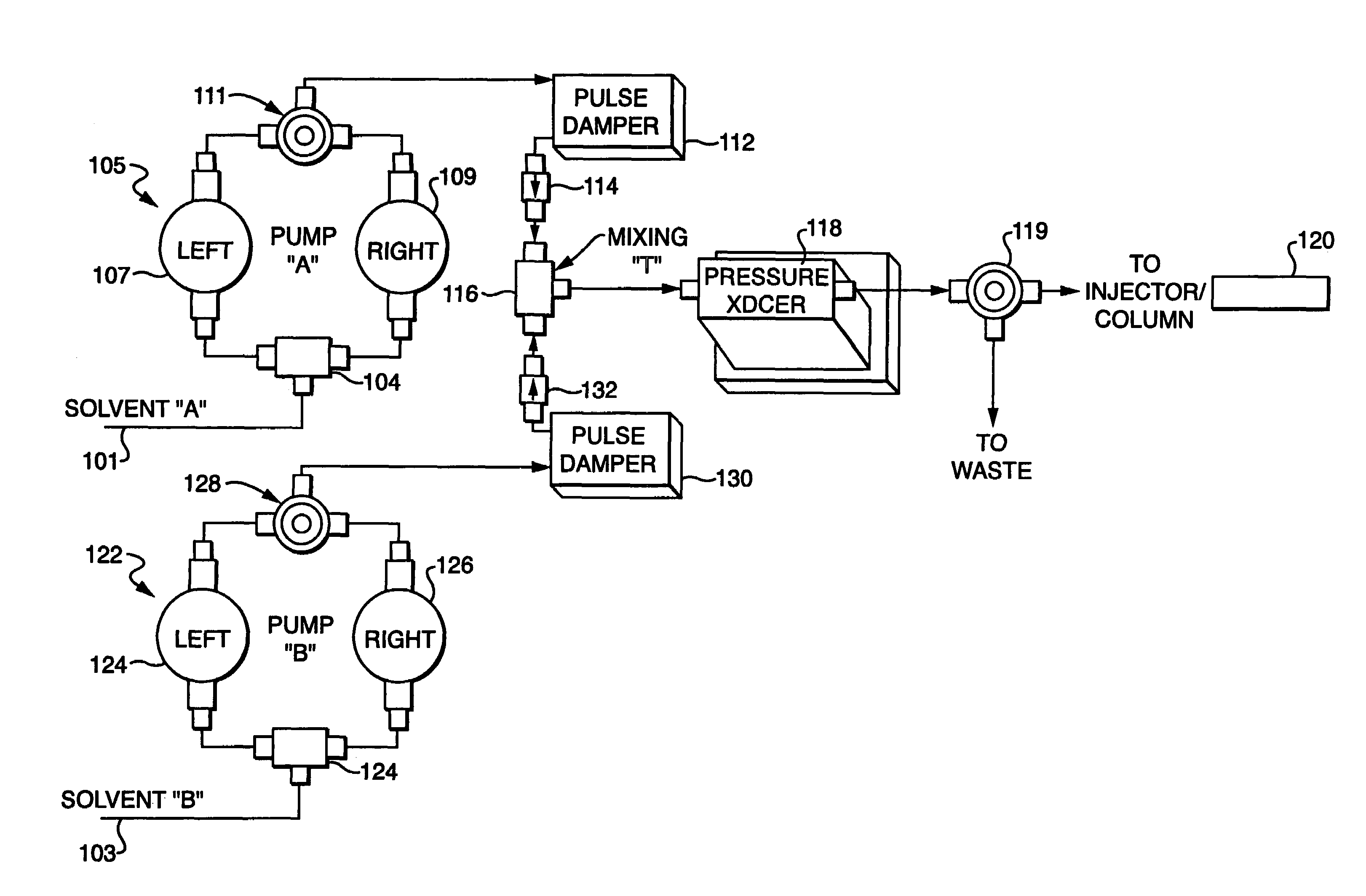
[0015]The present invention provides an improved method and apparatus for improving the compositional accuracy of high pressure gradient pumps for HPLC by approximation of infinite stroke volume with backflow prevented pulse dampening. The backflow prevention, according to the invention, adds sufficient minimum flow resistance thereby enhancing the performance of the pulse dampening over a wider range of flow rates resulting in consistent gradient performance.
[0017]The backflow preventors further ensure that the outlet check valves of the respective pump heads will experience sufficient backpressure allowing for their proper functioning. This sufficient backpressure is particularly helpful in systems having low flow rates when the backpressure generated by the column and tubing is limited. Additionally, backpressure allows the primary check valves of individual pumps to operate more consistently as the resulting backpressure ensures proper seating of the outlet check valve on the pump head that is off line.
[0018]The proper placement of a backflow preventor according to the invention reduces fluidic cross talk, optimizes the performance of in-line pulse dampers and enhances the performance of the high pressure pumps as shown in FIG. 3., which plots the delivery of a gradient marker from a solvent delivery system configured with backflow prevention according to the invention. As depicted in FIG. 3, the gradient deliveries are identical and correspond to the programmed gradient.
[0019]Advantageously, individual pumps deliver smooth flow by the addition of suitable pulse dampeners with the further use of backflow preventors that prevent fluidic cross talk between the two mobile phases. Because a pulse dampener is the fluidic equivalent of a low pass filter, when a small stroke volume is combined with a pulse dampener, the crossover perturbations occur at frequencies that are strongly attenuated. The differences between individual pump heads are effectively averaged by the use of pulse dampeners. Thus, the use of small stoke volumes with efficient pulse dampening provide for uniform blending of solvents in high pressure gradient systems.
[0020]In an alternative illustrative embodiment a capillary restrictor is used to generate backpressure to energize the pulse dampener. A capillary of fixed length and internal diameter provides sufficient backpressure over a certain range of flow rates. The use of a capillary restrictor in series with a check valve can be used for systems having consistent flow rates.
[0021]In a further alternative illustrative embodiment the check valves are incorporated into a mixing tee. This incorporation decreases the volume of the mobile phase within the gradient system and therefore decreases the delay volume of the gradient system.

Problems solved by technology

Known pumping systems exhibit some non-ideal characteristics which result in diminished separation performance and diminished run-to-run reproducibility.
Among the non-ideal pump characteristics exhibited in known pumping systems are, generally, fluctuations in solvent composition and / or fluctuations in volumetric flow rate.
Volumetric flow fluctuations present in known HPLC pumping systems disadvantageously cause retention time(s) to vary for a given analyte.
That is, the amount of time that an analyte is retained in the stationary phase fluctuates undesirably as a function of the undesirable volumetric flow fluctuations.
This creates difficulties in inferring the identity of a sample from the retention behavior of the components.
Fluctuations in solvent composition present in known HPLC pumping systems can disadvantageously result in interactions with the system's analyte detector and produce perturbations which are detected as if they arose from the presence of a sample.
This interference signal is summed with the actual signal attributable to the analyte, producing errors when the quantity of an unknown sample is calculated from the area of the eluting sample peak.
However, the assembly for driving the plunger is an elaborate combination of elements that can introduce undesirable motion in the plunger as it is driven, which motion makes it difficult to precisely control the solvent delivery system output and results in what is termed “noise” or detectable perturbations in a chromatographic baseline.
The delay volume is the volumetric overhead of the gradient solvent delivery system; it adds to the time required to complete the separation and to prepare the column for the next injection.
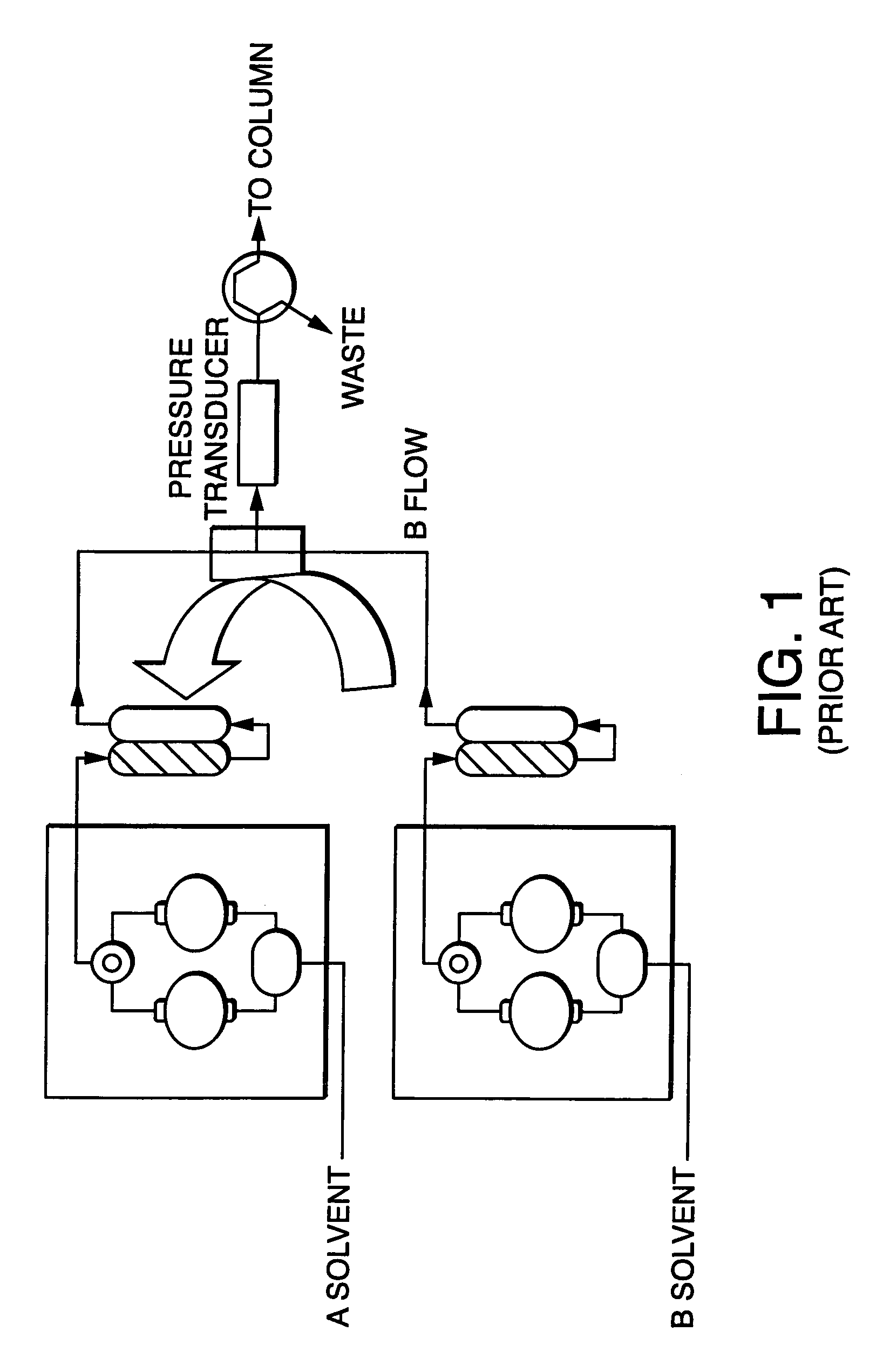
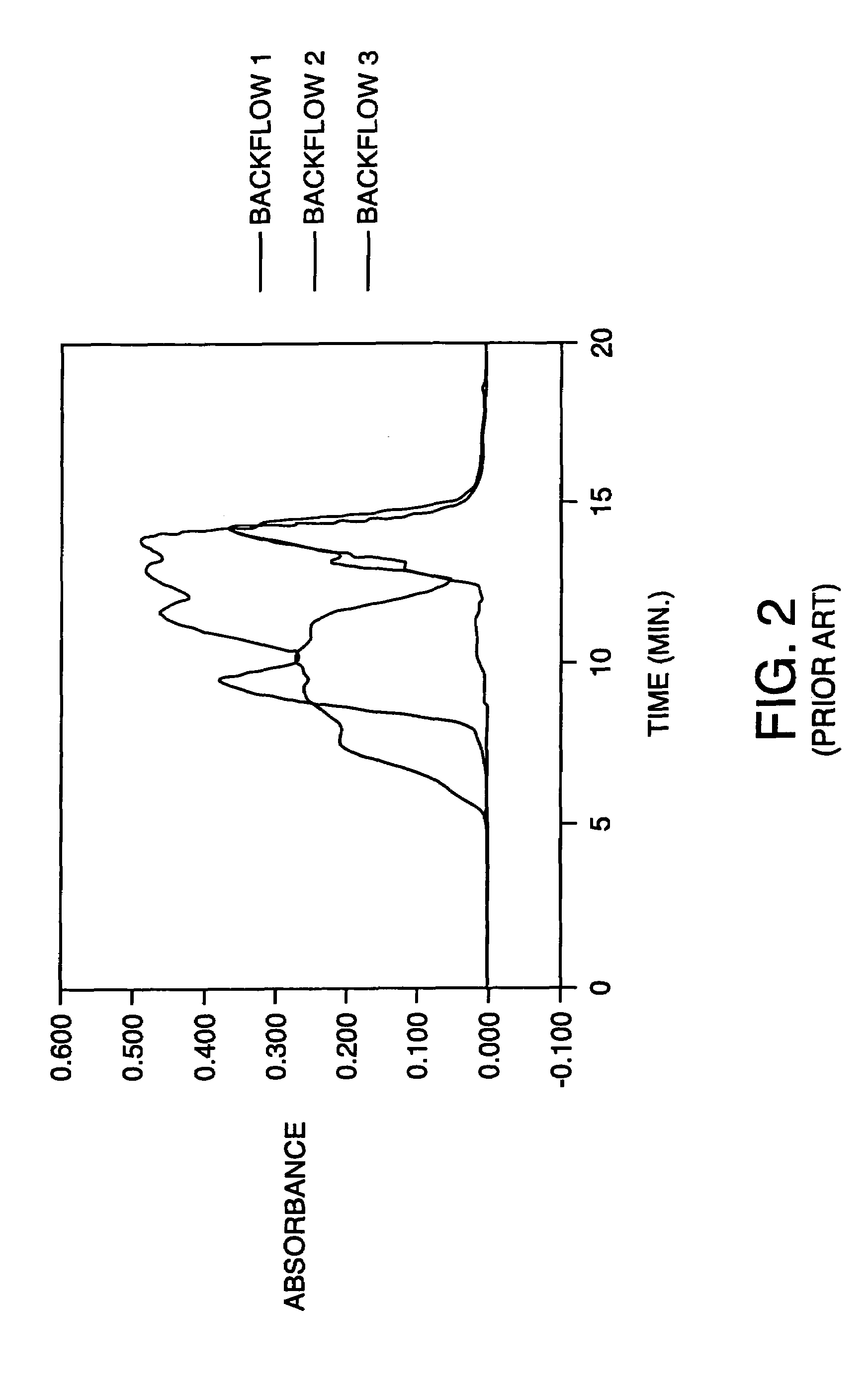
When individual pulse dampeners are placed up-stream from where output of the solvents meet and the total flow is small relative to the volume of the pulse dampeners, there will be significant crosstalk between the pumps since the two pumps are not synchronous in their respective piston crossovers.
As such, this up-stream placement of the pulse dampeners results in a compromised flow rate and composition.
This results in unsatisfactory and unpredictable separations which cannot be reproduced.
A capillary of fixed length and internal diameter provides sufficient backpressure to restrict, but unfortunately not prevent backflow, over narrow ranges of flow rates.
While this approach is useful in gradient systems having large volumes, smaller scale volumes are problematic.
The positioning of a pulse dampener after the common mixing tee greatly increases the delay volume within the gradient systems.

Method used


Image

  • Backflow prevention for high pressure gradient systems
  • Backflow prevention for high pressure gradient systems
  • Backflow prevention for high pressure gradient systems

Examples


Embodiment Construction

[0031]The present disclosure will be described in detail with respect to chromatographic applications with the understanding that embodiments of the present invention are directed to industrial and process control applications as well.

[0032]As shown in FIG. 4 the effect of pump crossover on solvent composition is illustrated. Within this illustration, the total flow is 1 mL / min. A first pump delivers ninety percent of the flow or approximately 900 μL / min. A second pump delivers ten percent of the flow or approximately 100 μL / min. The stroke volume is approximately 100 μL for both pumps. There are nine crossovers of the first pump to one crossover of the second pump to provide the desired composition. When the first pump crosses over there is a deficit in the first solvent of about 23 percent in flow rate and the composition is momentarily enriched in the second solvent. This deficit is illustrated by a first curve 301. A second curve 302 shows the effect of reducing the magnitude of...


PUM

PropertyMeasurementUnit
pressuresaaaaaaaaaa
stroke volumeaaaaaaaaaa
flow ratesaaaaaaaaaa

Abstract

Gradient performance with high pressure gradient solvent delivery system is optimized by approximation of infinite stroke volume of high pressure pumps by the addition of pulse dampening with backflow prevention to each high pressure pump. The backflow prevention adds sufficient minimum flow resistance, thereby enhancing the performance of the pulse dampening over a wider range of flow rates resulting in consistent gradient performance.

Description

FIELD OF THE INVENTION[0001]This application is a Divisional Application of Ser. No. 10 / 314,725, filed Dec. 9, 2002 now U.S. Pat. No. 6,780,315, the entire teachings of which are incorporated herein by reference.BACKGROUND OF THE INVENTION[0002]High-pressure liquid chromatography (HPLC) solvent delivery systems are used to source single-component liquids or mixtures of liquids (both known as “mobile phase”) at pressures which can range from substantially atmospheric pressure to pressures on the order of ten thousand pounds per square inch. These pressures are required to force the mobile phase through the fluid passageways of a stationary phase support, where separation of dissolved analytes can occur. The stationary phase support may comprise a packed bed of particles, a membrane or collection of membranes, a porous monolithic bed, or an open tube. Often, analytical conditions require the mobile phase composition to change over the course of the analysis (this mode being termed “gr...

Claims


Application Information

Patent Timeline
Patent Type & Authority Patents(United States)
IPC IPC(8): B01D15/08G01N30/10G01N30/32G01N30/36
CPCG01N30/32G01N30/10G01N30/36G01N2030/322G01N2030/328G01N30/34Y10T137/7838Y10T137/87684
Inventor ANDREWS, RICHARD W.RICHARDSON, HAL
Owner WATERS INVESTMENTS
Learn More