Laser cavity pumping method and laser system thereof

a laser system and laser cavity technology, applied in the direction of laser details, solid-state laser construction details, optical resonator shape and construction, etc., can solve the problems of not ensuring the control of the number of higher-order modes being excited, and limiting the extraction of the average power required. , the effect of improving efficiency

Inactive Publication Date: 2008-07-08
TRUMPF SCHWEIZ AG
View PDF7 Cites 10 Cited by
  • Summary
  • Abstract
  • Description
  • Claims
  • Application Information

AI Technical Summary

Benefits of technology

[0018]It is the object of the present invention to solve the above drawbacks and provide a pumping method of laser systems having an improved manufacture and better efficiency compared to common solutions.

Problems solved by technology

Once the absorption efficiency requirement of the pump light has been established, the laser systems so conceived do not ensure control of the number of higher order modes being excited, and consequently of the beam quality.
Thus, only the most external and energetically less significant circle of the cavity laser mode is subject to a non parabolic phase modulation and to the losses caused by repeated passes in the resonant cavity.
Providing such a source entails some critical factors, which may represent some drawbacks and limit the extraction of the average powers required in the range between 2 and 100 W or compromise the beam quality required at such operating powers.
A first more relevant drawback is due to the pumping process and laser action, which deposits residual heat in the active material.
In particular, the above phenomenon of thermal lens deteriorates laser power extraction, since the most external portion of the laser mode passing through the active material undergoes phase aberrations, which cause a net reduction of power circulating in the cavity, as well as a worsening of the laser beam quality.
In addition, operating a laser apparatus with an intensive thermal lens in a giant pulse operation, i.e. a repetitive Q-switching regime, may prove difficult.

Method used


Image

  • Laser cavity pumping method and laser system thereof
  • Laser cavity pumping method and laser system thereof
  • Laser cavity pumping method and laser system thereof

Examples


Embodiment Construction

[0039]The object of the present invention consists of an innovative structured pumping method co-linear to the resonator axis, specifically conceived for efficient operation of a laser cavity in a slightly multimode condition, with M2 of the output beam contained between 1.3 and 6; this pumping method is conceived as a function of the development of a laser device characterised by its simplicity and high operating flexibility; additionally, it implies considerable advantages in terms of thermal dissipation and operating stability with the changing wavelength of the pump source.

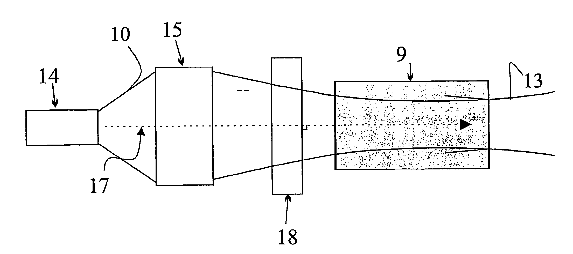
[0040]The pumping scheme provided by the method according to the present invention is schematically represented in FIG. 1; it consists of three separate subsystems, i.e. a pump source 14, a launching optic assembly 15 and an active medium 9 located inside a laser cavity.

[0041]The subsystem defined as the pump source 14 supplies a single light beam, i.e. the pump beam 10, which propagates along a pumping axis 1...


PUM


Abstract

A pumping method of discrete elements solid state laser systems pumped by semiconductor laser diodes, which sends a pump beam through an active medium, comprising a first face first crossed by said pump beam, and a second face met as second by the pump beam, a pumping axis being associated to the pump beam, the active medium being inserted in a cavity to which a cavity propagation axis is associated. The pumping axis coincides with the cavity propagation axis inside the active medium, and is perpendicular to an optical surface met by the pump beam after crossing the active medium, the optical surface being at least partially reflecting at the wavelength of the pump beam.

Description

BACKGROUND OF THE INVENTION[0001]The present invention relates to a pumping method of discrete elements solid state laser systems pumped by semiconductor laser diodes, which sends a pump beam through an active element comprising a first face first crossed by said pump beam, and a second face met as second by said pump beam, a pumping axis being associated to the pump beam, the active element being inserted in a cavity to which a cavity propagation axis is associated to.[0002]An apparatus developed according to the above method is also described by way of a non limiting example. Operation of such an apparatus can be in a continuous wave or pulsed regime through appropriate modulation of the electromagnetic field in the cavity.[0003]According to the conventional side pumping scheme of active crystal elements in solid state laser systems, the pumping light propagates and is absorbed into the active material along the crosswise direction to the propagation direction of the laser mode; t...

Claims


Application Information

Patent Timeline
Patent Type & Authority Patents(United States)
IPC IPC(8): H01S3/14H01S3/08H01S3/0941
CPCH01S3/0941H01S3/025H01S3/0405H01S3/042H01S3/0602H01S3/107H01S3/08H01S3/0805H01S3/094084H01S3/0621
Inventor DELL'ACQUA, STEFANOPICCINNO, GIULIANO
Owner TRUMPF SCHWEIZ AG
Why Eureka
Try Eureka