Photon counting CT detector using solid-state photomultiplier and scintillator

a detector and solid-state technology, applied in the field of radiographic detectors for diagnostic imaging, can solve the problems of inability to provide data or feedback as to the number and/or energy of photons detected, inability to provide energy discriminatory data or otherwise count the number and/or energy of photons actually received by a given detector element or pixel, and inability of photodiodes to discriminate between the energy, etc., to achieve improved saturation characteristics, low associated noise, and high gain

Active Publication Date: 2008-07-22
GENERAL ELECTRIC CO
View PDF3 Cites 54 Cited by
  • Summary
  • Abstract
  • Description
  • Claims
  • Application Information

AI Technical Summary

Benefits of technology

[0010]The present invention overcomes the aforementioned drawbacks by providing a CT detector module capable of providing photon count and energy data with improved saturation characteristics. The CT detector module includes a fast scintillator that does not saturate at the x-ray photon flux rates typically found in conventional CT systems. The CT detector module also includes a solid-state photomultiplier (SSPM) that provides a high gain with low associated noise to allow for photon counting and energy discrimination data in the detector module.

Problems solved by technology

A drawback of such detectors however is their inability to provide data or feedback as to the number and / or energy of photons detected.
A drawback of these detectors is their inability to provide energy discriminatory data or otherwise count the number and / or measure the energy of photons actually received by a given detector element or pixel.
Under the charge integration operation mode, the photodiode is not capable of discriminating between the energy level or the photon count from the scintillation.
However, there are varying problems that limit the use of these detectors.
In the case of APDs, there is additional gain need to enable photon counting, but with associated gain-instability noise, temperature sensitivity, and other reliability issues.
In the case of photomultiplier tubes, these devices are too large, mechanically fragile, and costly for high resolution detectors covering large areas as used in CT.
As such, these photomultiplier tubes have been limited to use in PET or SPECT systems.
A drawback of direct conversion semiconductor detectors, however, is that these types of detectors cannot count at the x-ray photon flux rates typically encountered with conventional CT systems.
The very high x-ray photon flux rate causes pile-up and polarization.
This type of pile-up results in a degradation of the energy resolution of the system.
In the second type of pile-up, the two or more events arrive close enough in time so that the system is not able to resolve them as distinct events.
In addition, pile-up leads to a more or less pronounced depression of counts in high x-ray flux, resulting in detector quantum efficiency (DQE) loss.
Direct conversion detectors are also susceptible to a phenomenon called “polarization” where charge trapping inside the material changes the internal electric field, alters the detector count and energy response in an unpredictable way, and results in hysteresis where response is altered by previous exposure history.
Above these thresholds, the detector response is not predictable and has degraded dose utilization that leads to loss of imaging information and results in noise and artifacts in x-ray projection and CT images.
What can be problematic, however, is that the bowtie filter may not be optimal given that a subject population is significantly less than uniform and can vary in shape.
Low x-ray flux in the projection will ultimately contribute to noise in the reconstructed image of the subject.
However, the signal-to-noise ratio of the resulting signal may be reduced, and the level of cross-talk will be disadvantageously significant due to the increased perimeter between sub-pixels.
Charge sharing may cause the photon to be missed entirely or mislabeled in energy.

Method used


Image

  • Photon counting CT detector using solid-state photomultiplier and scintillator
  • Photon counting CT detector using solid-state photomultiplier and scintillator
  • Photon counting CT detector using solid-state photomultiplier and scintillator

Examples


Embodiment Construction

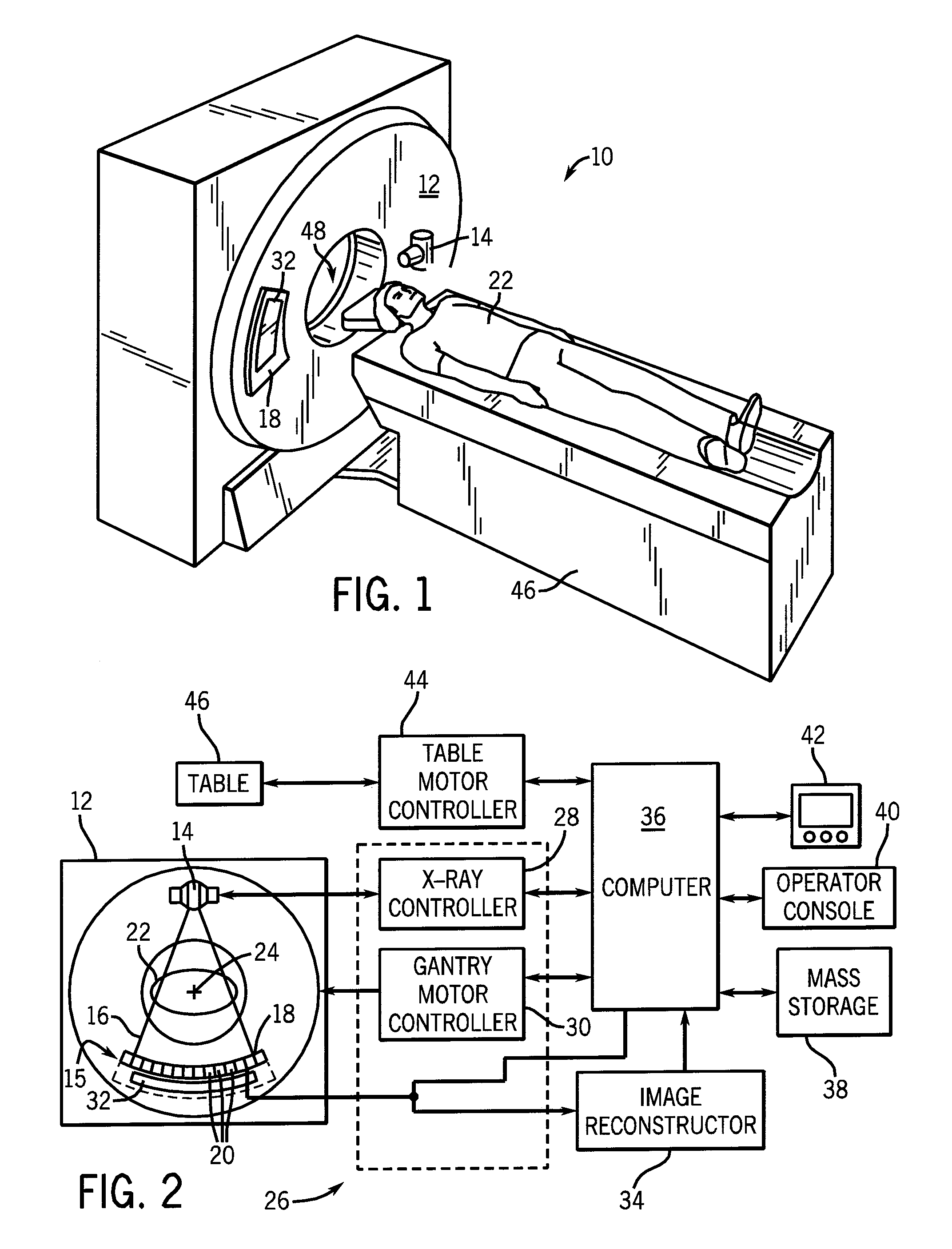
[0024]In accordance with one aspect of the present invention, a CT imaging system is provided. The CT imaging system includes a detector constructed to perform photon counting and energy discrimination of x-rays at the high flux rates generally associated with CT imaging.

[0025]The operating environment of the present invention is described with respect to a sixty-four-slice computed tomography (CT) system. However, it will be appreciated by those skilled in the art that the present invention is equally applicable for use with other multi-slice configurations. Moreover, the present invention will be described with respect to the detection and conversion of x-rays. However, one skilled in the art will further appreciate that the present invention is equally applicable for the detection and conversion of other high frequency electromagnetic energy. The present invention will be described with respect to a “third generation” CT scanner, but is equally applicable with other CT systems.

[0...


PUM


Abstract

A detector module for a CT imaging system includes a scintillator to convert x-rays to optical photons. The scintillator is optically coupled to a solid-state photomultiplier with internal gain to receive the optical photons and convert them into a corresponding electrical signal output.

Description

BACKGROUND OF THE INVENTION[0001]The present invention relates generally to radiographic detectors for diagnostic imaging and, more particularly, to a CT detector module capable of providing photon count and energy data with improved saturation characteristics.[0002]Typically, in radiographic imaging systems, such as x-ray and computed tomography (CT), an x-ray source emits x-rays toward a subject or object, such as a patient or a piece of luggage. Hereinafter, the terms “subject” and “object” may be interchangeably used to describe anything capable of being imaged. The beam, after being attenuated by the subject, impinges upon an array of radiation detectors. The intensity of the attenuated beam radiation received at the detector array is typically dependent upon the attenuation of the x-rays. Each detector element of the detector array produces a separate electrical signal indicative of the attenuated beam received by each detector element. The electrical signals are transmitted t...

Claims


Application Information

Patent Timeline
Patent Type & Authority Patents(United States)
IPC IPC(8): A61B6/00
CPCA61B6/032A61B6/4241G01T1/2018G01T1/1642A61B6/482G01T1/20184G01T1/20182
Inventor SHORT, JONATHAN D.POSSIN, GEORGE E.LEBLANC, JAMES W.RODRIGUES, ROGERIO G.BURR, KENT C.COUTURE, AARON J.LI, WEN
Owner GENERAL ELECTRIC CO
Why Eureka
Try Eureka