Multi-antenna transmission method and system

a transmission method and multi-antenna technology, applied in the field of multi-antenna transmission methods and systems, can solve the problems of affecting the accuracy (or delay) of feedback signaling, the inability to provide multiple receive antennas, and the burden on the downlink channel of the projected data services (e.g. internet), so as to achieve good channel estimation performance and increase the transmission gain

Inactive Publication Date: 2008-07-22
WSOU INVESTMENTS LLC
View PDF9 Cites 212 Cited by
  • Summary
  • Abstract
  • Description
  • Claims
  • Application Information

AI Technical Summary

Benefits of technology

[0023]It is therefore an object of the present invention to provide a multi-antenna transmission method and system by means of which the transmission gain can be increased while maintaining a good channel estimation performance.
[0032]Accordingly, the best antennas are selected from the antenna array and used to transmit the transmission signal so as to perform a transmit diversity transmission or a beamforming operation. Thus, the chance that the corresponding selected channels (i.e. antennas or beams) are good can be increased with the number of predetermined channels (i.e. antennas or beams) based on which the selection is performed. Thus, the transmission gain approaches that of a space-time coding scheme using the predetermined number of channels, while the actual signal transmission is performed by using only the selected channels. The receiver uses the channel impulse response of the selected best received channels in the subsequent feedback control. After the initial selection based on the predetermined number of channels (e.g. all channels), the total power is supplied to the best channels, i.e. to transmit the transmission signal via the selected best channels. Thereby, power efficiency and channel power available for performing the channel estimation can be increased.
[0033]The at least two selected antennas or beams may be controlled at least in part based on another feedback information received from said receiving means. Thus, the same procedures can be used for transmit diversity and beamforming cases. Only the parameters at the transmission end have to be changed (e.g. redefinition of the received FSMs). In the beamforming case, the feedback control (closed-loop diversity) on the basis of the other feedback information leads to a digital or stepwise beamforming. Thus, the advantages of digital beamforming (e.g. reduced cusping loss due to elimination of fixed beam worst case) can be obtained without the need of calibration at the transmitting end.
[0034]Since the feedback information and the other feedback information can be signaled using existing functions of the receiving user equipment (e.g. mobile station), the user equipments do not have to be modified, at least not to a large extent. The receiver even does not have to know which kind of antenna control is performed. Thereby, diversity and antenna gain can be adapted to different propagation environments. In micro cell environments (i.e. small cell areas), diversity is preferred due to the small delay spread and typically large angular spread of the mobile stations located in the corresponding cell area. In macro cell environments (i.e. large cell areas), the radio channel typically provides “enough” path-diversity, such that capacity and coverage improvements can be achieved by a beamforming operation (i.e. increasing the antenna gain e.g. by directing the transmission beam towards the mobile station).
[0047]As an alternative, fixed antenna or beam pairs may be selected in said selection step. In this case, only one bit is required for selecting two channel pairs out of four total channels. Thereby, control speed can be increased.
[0048]As a further alternative, variable number of antennas or beams may be selected. Then, the space-time coding scheme can be adapted to the number of good channels, to thereby further increase diversity gain.

Problems solved by technology

However, the capacity demand imposed by the projected data services (e.g. Internet) burdens more heavily the downlink channel.
Bearing in mind the strict complexity requirements of terminals, and the characteristics of the downlink channel, the provision of multiple receive antennas is not a desired solution to the downlink capacity problem.
While many of these extensions are straightforward, most of them are applicable only in very low mobility environments, since the accuracy (or delay) of the feedback signaling is often compromised.
In addition, it has to be considered that unnecessary transmissions might be performed if the channels of the corresponding antennas are in deep fades.
If m is large, the power per antenna is low and thus the performance of the channel estimation operation at the receiver will suffer due to the low SNR (Signal to Noise Ratio).

Method used


Image

  • Multi-antenna transmission method and system
  • Multi-antenna transmission method and system
  • Multi-antenna transmission method and system

Examples


Embodiment Construction

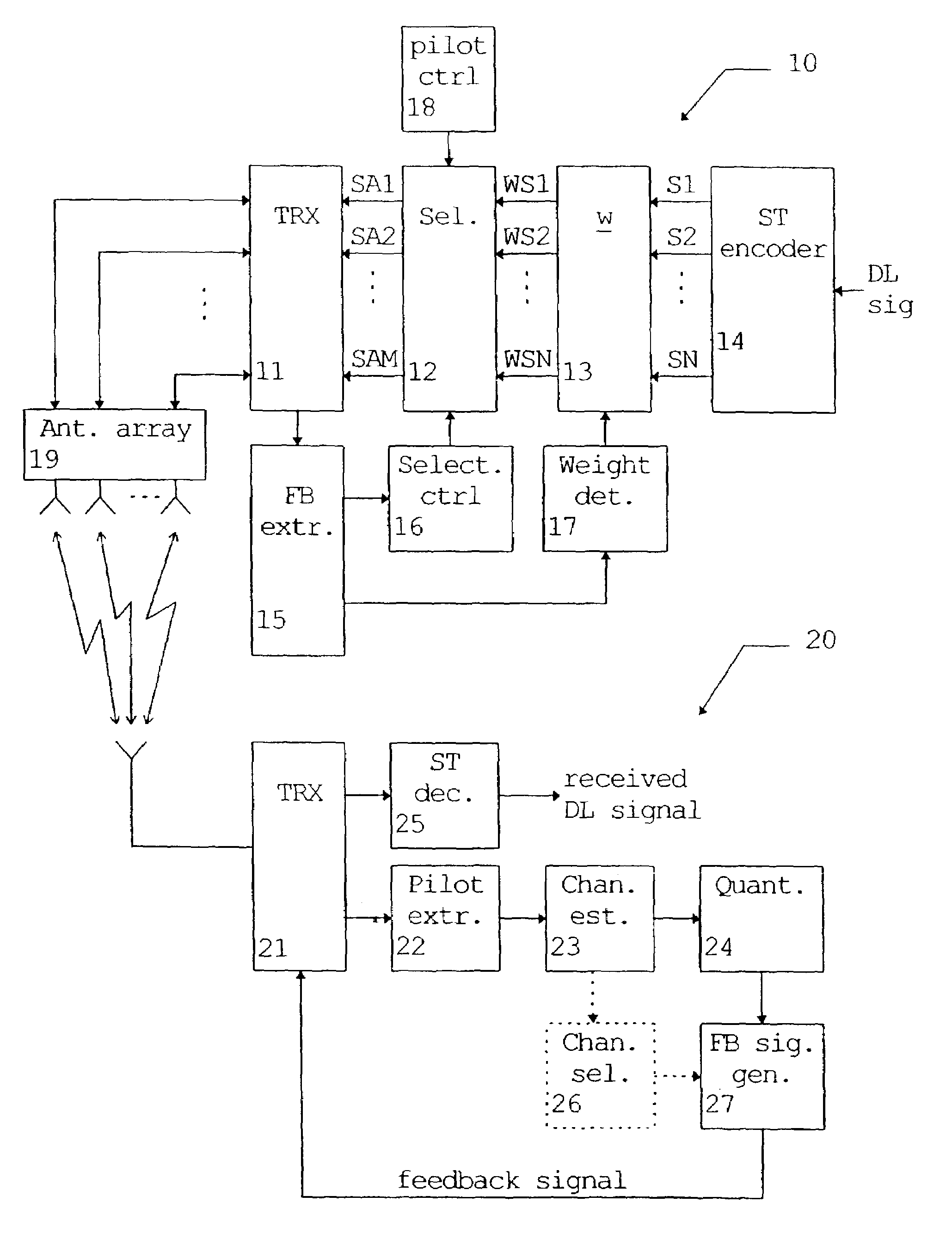
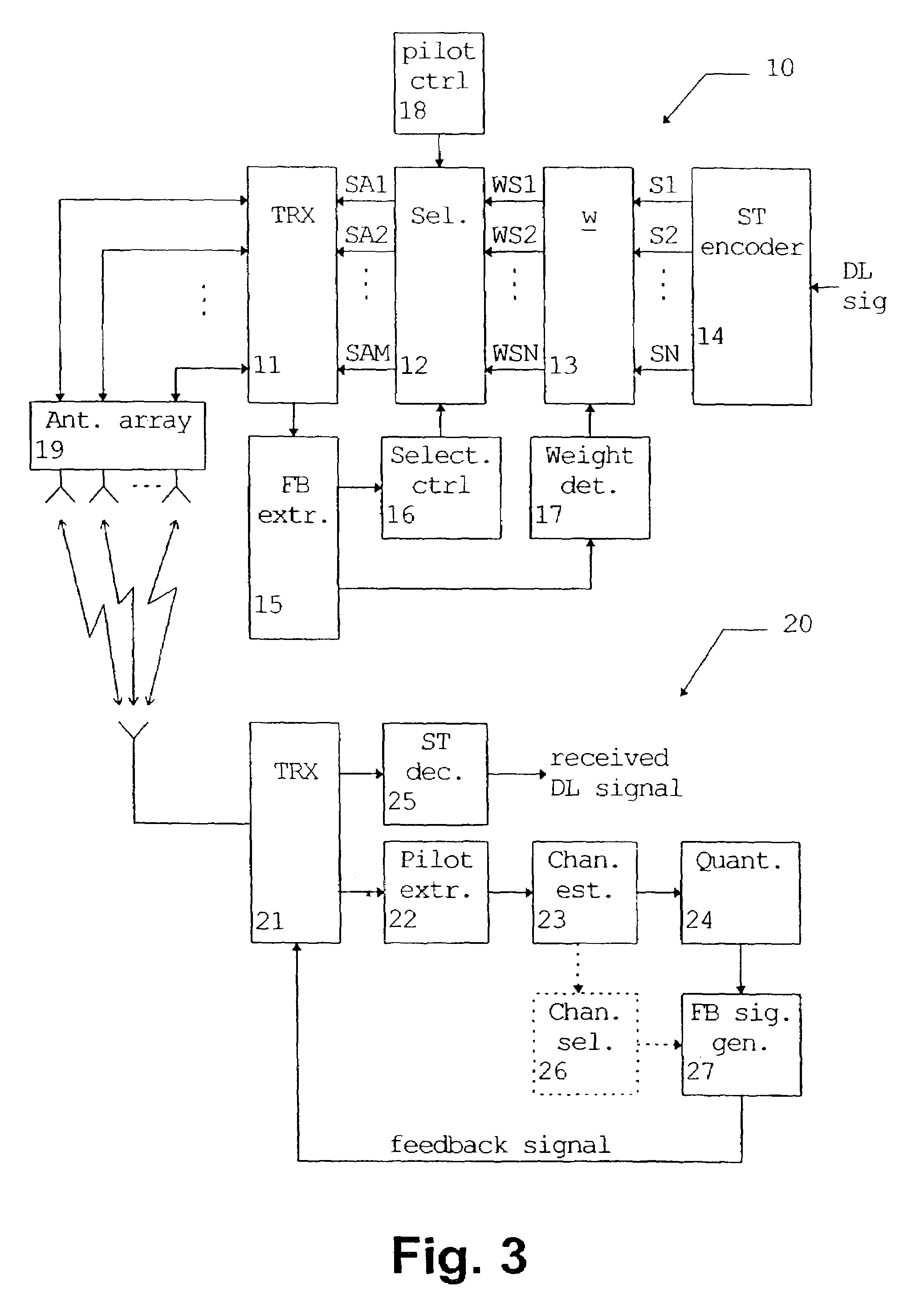
[0058]In the following, the preferred embodiment of the method and system according to the present invention will be described on the basis of wireless transmission between a base station 10 and a mobile station or terminal 20 of a WCDMA system. According to FIG. 3, the base station 10 comprises an antenna array 19 comprising M antenna elements. It is noted that the antenna array may consist of closely spaced antenna elements (interelement spacing e.g. λ / 2) or widely spaced diversity antennas. The array may also include a phasing network such as a Butler matrix in order to generate beams. Furthermore, antennas with orthogonal polarizations may also be used for other diversity antennas.

[0059]The antenna elements of the antenna array 19 are fed by a transceiver TRX 11 which supplies M parallel antenna signals SA1 to SAM to the antenna array 19. The parallel signals SA1 to SAM selected or generated by a selector 12 on the basis of N weighted signals WS1 to WSN supplied from a weighting...


PUM


Abstract

The present invention relates to a method and system for transmitting a transmission signal from an antenna array (19) to a receiving means (20) of a wireless communication system, wherein a signal quality measurement is performed at the receiving means (20) for predetermined antennas or beams of said antenna array (19). Based on a feedback information derived from the signal quality measurement, at least two of the predetermined antennas or beams of the antenna array (19) are selected. The selected antennas or beams are used for transmitting said transmission signal according to a transmit diversity or beamforming scheme. Thus, spectral efficiency and diversity gain can be enhanced by using only selected ones of the predetermined antennas or beams.

Description

PRIORITY CLAIM[0001]This is a national stage of PCT application No. PCT / EP00 / 03137, filed on Apr. 7, 2000. Priority is claimed on that application.FIELD OF THE INVENTION[0002]The present invention relates to a multi-antenna transmission method and system for a wireless communication system such as the Universal Mobile Telecommunications System (UMTS).BACKGROUND OF THE INVENTION[0003]Wideband Code Division Multiple Access (WCDMA) has been chosen as the radio technology for the paired bands of the UMTS. Consequently, WCDMA is the common radio technology standard for third-generation wide-area mobile communications. WCDMA has been designed for high-speed data services and, more particularly, Internet-based packet-data offering up to 2 Mbps in indoor environments and over 384 kbps for wide-area.[0004]The WCDMA concept is based on a new channel structure for all layers built on technologies such as packet-data channels and service multiplexing. The new concept also includes pilot symbols...

Claims


Application Information

Patent Timeline
Patent Type & Authority Patents(United States)
IPC IPC(8): H04B7/02H04B17/00H04B7/06H04L1/06
CPCH04B7/06H04L1/0618H04B7/0691H04B7/061H04B7/0617H04B7/065H04B7/0669H04B7/0634
Inventor KESKITALO, ILKKAYLITALO, JUHAKATZ, MARCOS
Owner WSOU INVESTMENTS LLC
Why Eureka
Try Eureka