Method of converting a direct current voltage from a source of direct current voltage, more specifically from a photovoltaic source of direct current voltage, into a alternating current voltage

a direct current voltage and photovoltaic source technology, applied in the direction of power conversion systems, ac network circuit arrangements, electrical apparatus, etc., can solve the problems of reducing the efficiency of the circuit, and causing further losses, etc., to achieve simple low-loss circuitry, reduce material cost, and high efficiency

Active Publication Date: 2008-08-12
SMA SOLAR TECH AG
View PDF9 Cites 47 Cited by
  • Summary
  • Abstract
  • Description
  • Claims
  • Application Information

AI Technical Summary

Benefits of technology

[0013]It is the object of the present invention to indicate a method of the generic type by which high-frequency voltage fractions at the connection terminals of the generator are avoided on the one side and which, on the other side, allows for simple low-loss circuitry and, as a result thereof, for high efficiency. It furthermore aims at reducing the material cost and at increasing reliability.
[0015]The method of the invention permits to readily avoid high-frequency voltage fractions at the connection terminals of the direct current voltage intermediate circuit using therefore but one additional component (as compared to a simple H-bridge having four switching elements and four free-wheeling diodes). The complexity of the circuit is reduced over an H-bridge having additional connection paths (according to DE 102 21 592 A1 with six switching elements and six free-wheeling diodes), as but one semiconductor switching element with associated gating unit is needed instead of two additional semiconductor switching elements including gating units and two additional diodes (overall, only five switching elements with five free-wheeling diodes). Additional costs and the probability of failure are minimized as a result thereof.
[0017]The method of the invention makes it possible to have an asymmetric operation without high-frequency disturbances, more specifically if, according to an advantageous embodiment of the invention, the bridge circuit is gated in such a manner that the additional switching element located in the direct current voltage circuit is clocked in synchronism with a lower switch of the one bridge half during one half-wave while being clocked in synchronism with a lower switch of the other bridge half during the other half wave. Accordingly, the additional switch is clocked simultaneously with only one single switch.
[0018]Asymmetric operation permits to minimize losses and to improve the efficiency of the circuit. In accordance with this advantageous embodiment, the method of the invention combines at minimum component expense the advantages of a simple H-bridge circuit with asymmetric clocking exhibiting good efficiency with the advantages of a simple H-bridge circuit with symmetric clocking that avoids high-frequency signals at the terminals of the generator.
[0019]As contrasted with the symmetric clocking, a zero voltage state occurs like with asymmetric clocking since the voltage at the output terminals of the inverter are commutated between +U, zero, −U. As a result thereof, the hysteresis losses in the line reactors are reduced and the partial load efficiency in particular is improved as well.
[0022]By providing an anti-parallel diode of the additional switch that does not act as a free-wheeling diode or that is not engaged, like the lower free-wheeling diodes of the clocked switches, which are not engaged either in the normal case, the semiconductors used can be optimized. As a result thereof, semiconductor components can be used which, although they have unfavourable diode properties, exhibit good switching properties and low forward losses. As a result, the latest MOSFET-semiconductor components can be utilized for the switching elements to be clocked, said components permitting to further optimize efficiency and reduce cost.

Problems solved by technology

The circuit as configured does not avoid high-frequency voltages and does not eliminate EMC problems.
This solution results in quite high hysteresis losses in the reactors so that the efficiency of the circuit is reduced.
Further losses also occur because two switching elements are switched on and off concurrently and because, at free-wheeling state, the current flows into the direct current voltage intermediate circuit through two free-wheeling diodes.
At free-wheeling state, the direct current voltage in the intermediate circuit acts as a reverse voltage, which results in an increased current ripple and in an increased power loss.
This asymmetric gating however generates high-frequency potential fluctuations at the terminals of the photovoltaic generator which worsen the EMC behaviour of the generator.
Accordingly, the two drawbacks are avoided at the price of a more complex circuitry due to the much greater number of components which translates into a less reliable circuit and in increased material cost.

Method used


Image

  • Method of converting a direct current voltage from a source of direct current voltage, more specifically from a photovoltaic source of direct current voltage, into a alternating current voltage
  • Method of converting a direct current voltage from a source of direct current voltage, more specifically from a photovoltaic source of direct current voltage, into a alternating current voltage
  • Method of converting a direct current voltage from a source of direct current voltage, more specifically from a photovoltaic source of direct current voltage, into a alternating current voltage

Examples


Embodiment Construction

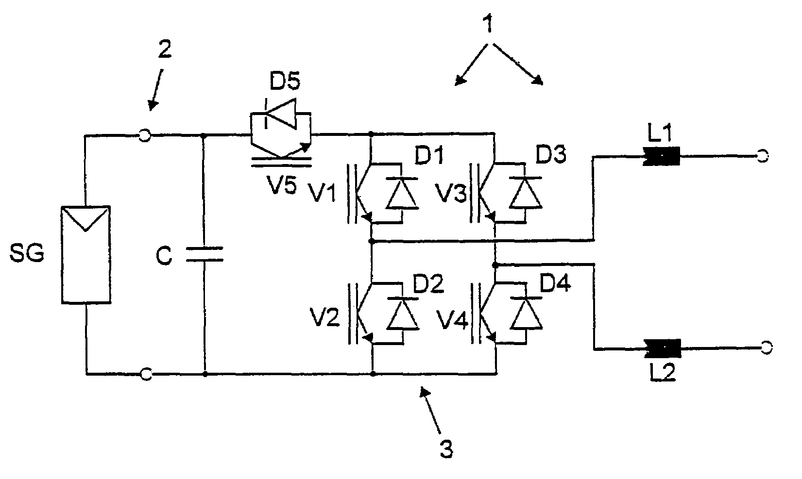
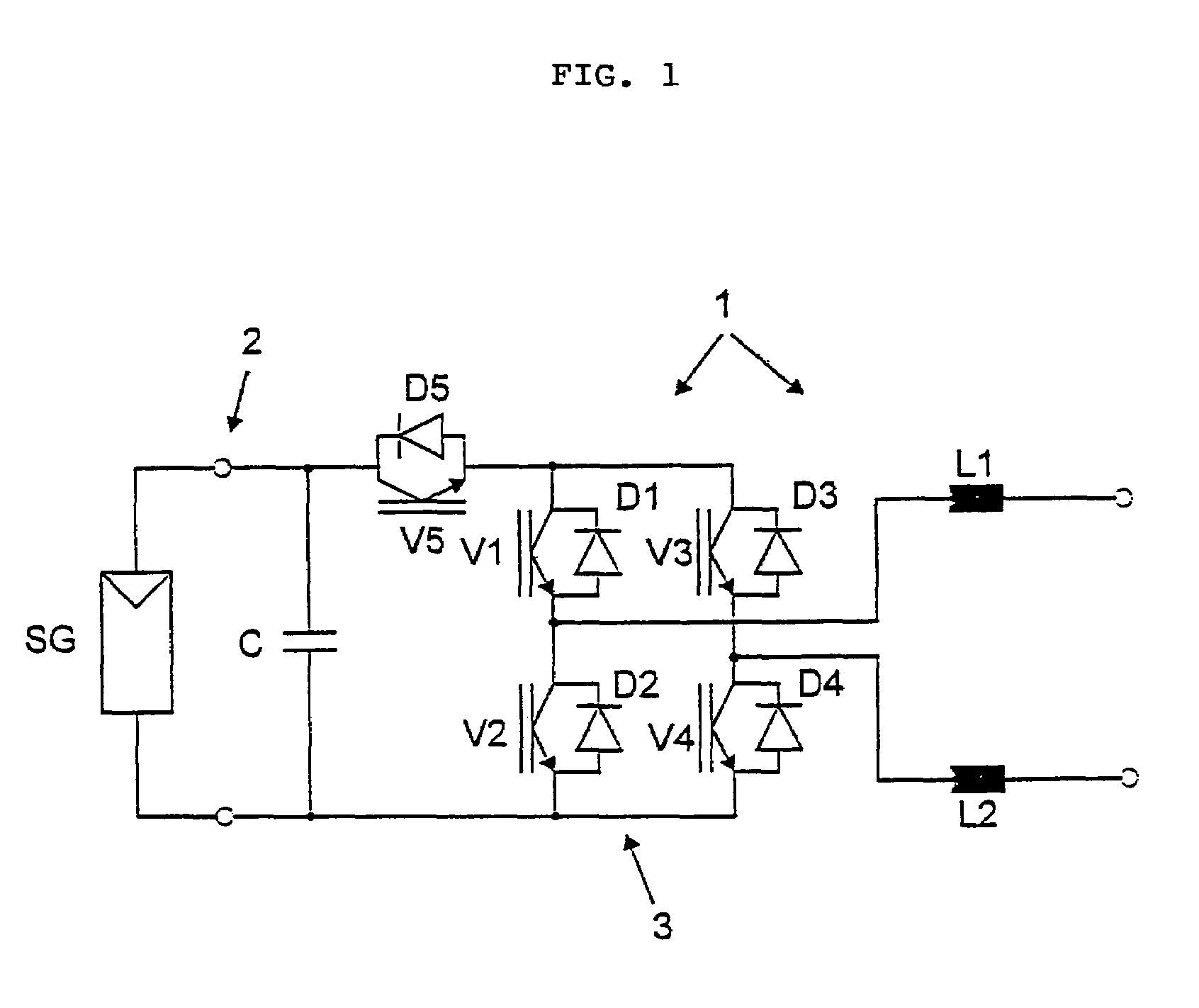
[0030]FIG. 1 shows an inverter 1 of the invention with a solar generator SG or with a photovoltaic generator. This circuit allows for a method of converting a direct electric current of a photovoltaic source of direct current into an alternating current at a frequency of 50 Hz for example.

[0031]At the input terminals 2 of the inverter 1, a filter capacitor C or storage capacitor is connected in parallel to the solar generator SG. Together with the capacitor C, the solar generator SG forms a direct current voltage intermediate circuit or a DC-circuit. The inverter has an H-bridge 3 with four semiconductor switching elements V1-V4 and one additional switch V5. Free-wheeling diodes D1-D5 are connected in parallel to the switching elements V1-V5. Two reactors L1 and L2 are located at the bridge branch in the alternating current voltage part.

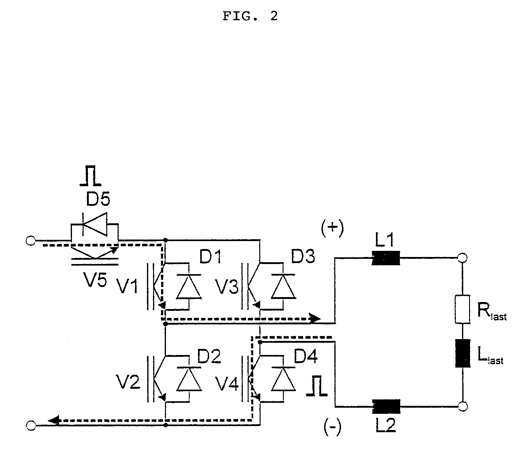
[0032]The upper switching elements V1 and V3 are gated at a mains frequency of 50 Hz for example whereas the lower switching elements V2 and V4 are ...


PUM


Abstract

An inverter is devised to avoid high-frequency voltages at input terminals and to allow good efficiency thanks to its simple and cost-optimized circuit layout. This is achieved by a method of converting a direct current voltage, more specifically from a photovoltaic source of direct current voltage, into an alternating current voltage at a frequency through a bridge circuit comprising switching elements (V1-V 4) and free-wheeling elements (D1-D4), said switching elements (V1-V4) being on the one side gated at the frequency and on the other side clocked at a high clock rate, a direct current voltage circuit, an alternating current voltage circuit and a plurality of free-wheeling phases being provided. It is provided that, during the free-wheeling phases, the alternating current voltage circuit is decoupled from the direct current voltage circuit by means of a switching element disposed in the direct current voltage circuit, a free-wheeling current flowing through one of the free-wheeling elements (D1) in the bridge circuit when in the decoupled state.

Description

BACKGROUND OF THE INVENTION[0001]1. Field of the Invention[0002]The invention relates to a method of converting a direct current voltage of a source of direct current voltage, more specifically of a photovoltaic source of direct current voltage, into an alternating current voltage at a frequency through a bridge circuit comprising switching elements and free-wheeling elements.[0003]2. Description of the Prior Art[0004]The document DE 197 32 218 C1 describes a transformerless inverter circuit arrangement with an inverting buck-boost converter circuit and a non-inverting converter circuit. Such type inverters are used for coupling photovoltaic systems. The circuit comprises a direct connection that is steady in terms of potential, that is, a conductor connection that remains at a fixed potential. At need, it is possible to use this direction connection as the neutral of the system between one of the two direct current connection terminals and one of the alternating current connection ...

Claims


Application Information

Patent Timeline
Patent Type & Authority Patents(United States)
IPC IPC(8): H02M7/5387H02M1/12H02M7/00H02M7/48H02M7/537
CPCH02M7/48Y02E10/563H02J3/383H02J2300/24H02J3/381Y02E10/56
Inventor VICTOR, MATTHAISGREIZER, FRANKBREMICKER, SVENHUBLER, UWE
Owner SMA SOLAR TECH AG
Why Eureka
Try Eureka