[0019]The
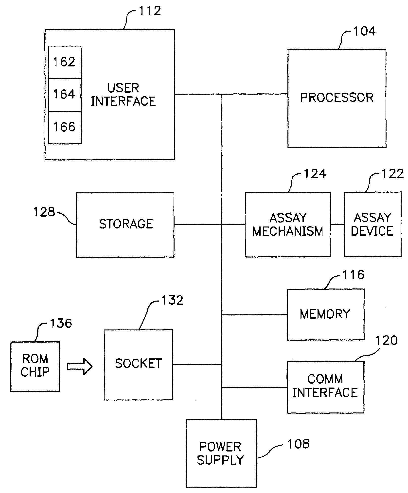
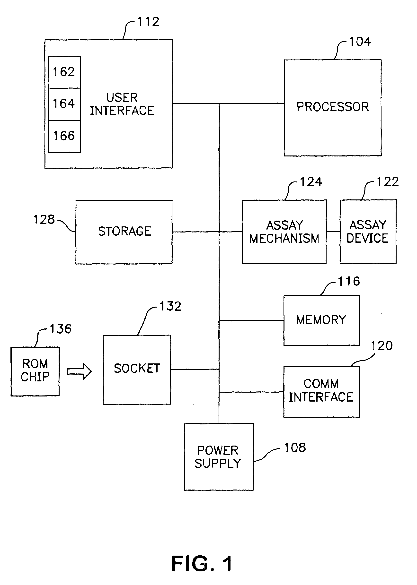
assay mechanism according to one embodiment includes a motorized mechanism for transporting the
assay device in the fluorometer. Examples of such a motorized mechanism include, for example, those as described in U.S. Pat. No. 5,458,852 and co-pending U.S. patent application Ser. No. 08 / 458,276, titled “Devices For Ligand
Receptor Methods,” which are incorporated herein by reference. The movement of the
assay device in the fluorometer functions to position the diagnostic lane of the device with an optical block so that one or more fluorescent areas or zones of the assay device can be measured. The degree or presence of
fluorescence in the diagnostic lane is related to the concentration or presence of
analyte in the sample. The optical block can include a
light source,
detector and
optics used to excite the sample as well as to sense the
fluorescence of the excited sample. In one embodiment, the sample is disposed on the assay device. The assay mechanism can provide the capability to transport the assay device along the optical block such that fluorescence of one or more of a plurality of zones on the diagnostic lane of the device can be measured. As such, one
advantage of the invention according to this embodiment is that enhanced testing algorithms can be utilized, if desired, in measuring the fluorescence of the sample.
[0020]An additional
advantage of the invention is that the communications interface can be used to allow the fluorometer to be interfaced to networks such as, for example, a hospital or other health
care facility network, or other
information networks whereby the fluorometer can retrieve data which may be needed to conduct tests and download other data including the test results. Additionally, the communications interface can be used to interface with the fluorometer to a stand alone computer such as, for example, a
personal computer or an office or a home office computer. In these configurations, the fluorometer can utilize the
processing and
peripheral capabilities of the stand alone computer or network resources to supplement its own
processing and interface capabilities. In yet another configuration, the fluorometer can interface with an existing instrument that is interfaced to a network, such as, for example, an instrument in a hospital
emergency department or
critical care unit that dispenses medications for use by the hospital personnel.
Interfacing the fluorometer to an existing instrument has advantages in that the interface of the fluorometer to the instrument can be one specific code, whereas the instrument interface code can be varied depending on the location of the instrument, for example, in different hospitals with different
software interface codes.
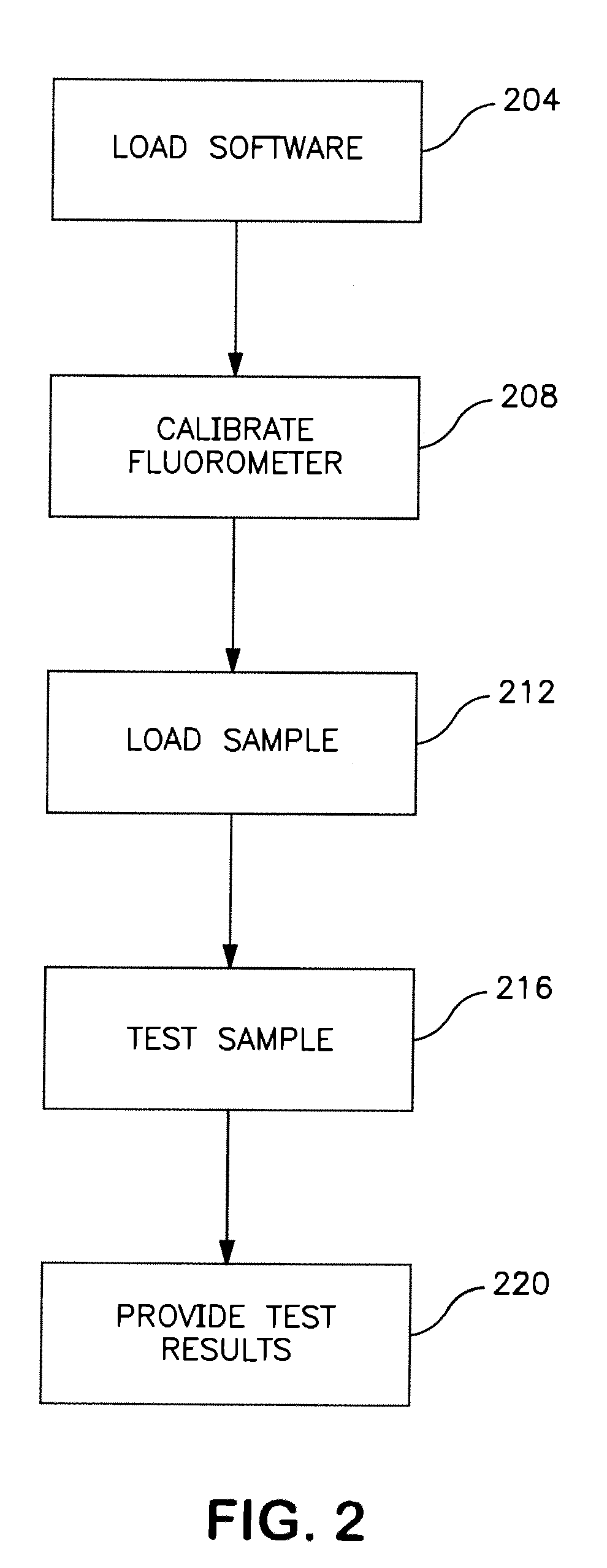
[0021]For example, in one embodiment, the fluorometer can be operated as a portable hand-carried piece of
test equipment that is used to test samples of blood. The portable, hand-carried unit can then be interfaced to a computer or
computer network to upload test results or to simply communicate other data associated with the test and to use the processing power of the computer or
computer network to perform some or all of the actual test processing. In yet another example,
test data sets or other pertinent information can be downloaded from the outside entity to provide the fluorometer with guidance as to tests to be conducted on a particular sample. This guidance can be in the form of complete test instructions or simply an identification of a test to be performed for which the instructions are stored internally to the fluorometer. In another example, the data communicated to a network can be utilized in real time to diagnose and treat acute care patients.
[0022]Yet another feature of the invention is that it provides an encoded tag on the assay device such as, for example, a bar code
label or magnetic strip to allow sample, test or
reagent information to be encoded. Sample information can include, for example, an identification of the sample and
sample type, an identification of the patient from which the sample was drawn, an indication of the test or tests to be performed for the sample, as well as other data, as desired.
Reagent information can include the type of reagents in a device, lot specific information, such as calibration information and expiration dating. Once a sample is correctly labeled, there is no longer a need for manual user intervention to enter this information. In
fully automated embodiments, this information is stored along with test results and other pertinent information to create and maintain an accurate
record of the tests and test results. As such, the chance for operator error in incorrectly identifying a sample or otherwise incorrectly entering information regarding a test, is minimized. Additionally, test results and other data relating to the test can be automatically stored along with the
patient identification and other associated information such that data for a patient can easily be accessed.
[0023]Another embodiment of the invention is to utilize an
encoder, such as for example a magnetic strip
encoder, in the instrument to
encode information on an assay device. For example,
patient information, including patient number, tests to be performed and the like can be entered through the keypad of the instrument or via a centralized computer that downloads the information to the fluorometer. The
encoder records the information onto the assay device, such that when the user inserts the assay device into the fluorometer, a reader reads the information on the assay device and combines the assay results with the encoded information. The combined information can be stored in the fluorometer and it can be communicated to a network for real time or later analysis.
[0024]Yet another feature of the invention is that internal data storage can be provided so that
patient information and test results can be tracked in the form of a history log. For example, in a portable hand-held environment, a user or
technician may test several samples of blood in a given time interval. The test results, along with the identification of the patient, can be stored in the local
database such that a history log of tests and test results are maintained. This history log can then be downloaded via the communications interface or onto a
removable media.

