Method and system for real-time monitoring and controlling height of deposit by using image photographing and image processing technology in laser cladding and laser-aided direct metal manufacturing process

a technology of image processing technology and laser cladding, which is applied in the direction of instrumentation, programme control,foundry moulding apparatus, etc., can solve the problems of difficult 3d shape generation from cad, process parameters affecting the height of the cladding layer, and the height of the laser cladding layer

Inactive Publication Date: 2008-09-09
INSSTEK
View PDF13 Cites 17 Cited by
  • Summary
  • Abstract
  • Description
  • Claims
  • Application Information

AI Technical Summary

Benefits of technology

[0024]Still another object of the present invention is to provide a method and apparatus, which is advantageous in that the method and apparatus can be applied to laser surface modification, such as laser surface alloying and laser cladding, and laser multi-layer cladding in which a cladding layer of 2 mm or more is formed through repeated laser cladding, as well as laser-aided direct metal manufacturing.

Problems solved by technology

Since it is difficult to generate 3D shapes from CAD data through conventional manufacturing processes in which a material is cut or a molten material is poured into and solidified in a mold, Materials Incress Manufacturing (MIM) has to be employed.
However, the height of the laser cladding layer is affected by a large number of process parameters, such as a laser power, the mode and size of a laser beam, the traverse speed of a specimen, the characteristics of cladding powder, powder feeding rate, the falling speed of powder, the overlapping factor of cladding beads, the kinds or amounts of various auxiliary gases supplied, etc.
Accordingly, in order to obtain the height of the cladding layer corresponding to 2D sectional information, there is technical difficulty that process parameters affecting the height of the cladding layer should be controlled while the position of a molten pool is monitored in real time.
However, when the molten pool does not reach the target height, light irradiated from the molten pool is blocked by the mask, so the phototransistor cannot detect any light.
At this time, there occurs a problem that a normal laser power is generated.
Accordingly, the cladding layer at this position is coated to be rather thicker or higher and the repeated performance of the laser cladding at this position causes the problem to be worse, thus deteriorating the precision of shaping.
However, when the 3D shape is formed using 2D sectional information of a variable thickness and / or height, there occurs a problem that the optical detection device should be arranged and corrected whenever the height of the cladding layer is varied.
In addition, a laser power control method is a laser beam On / Off method in which the duration time of a laser pulse is controlled, so it is difficult to apply the technology to a continuous wave laser generator.

Method used


Image

  • Method and system for real-time monitoring and controlling height of deposit by using image photographing and image processing technology in laser cladding and laser-aided direct metal manufacturing process
  • Method and system for real-time monitoring and controlling height of deposit by using image photographing and image processing technology in laser cladding and laser-aided direct metal manufacturing process
  • Method and system for real-time monitoring and controlling height of deposit by using image photographing and image processing technology in laser cladding and laser-aided direct metal manufacturing process

Examples


application example 1

[0090]FIG. 12 is a photograph showing simple metal parts manufactured by the method and apparatus of the present invention. A substrate having used in this manufacturing Was stainless steel (SUS 316), and a cladding material was a chromium-molybdenum hot-work die steel, H-13 tool steel (SKD 61), which is an alloy being commonly used as a material of die casting mold. A fine structure of 100% can be obtained by the method of the present invention, and the mechanical characteristics of the product were similar or superior to those of wrought materials.

application example 2

[0091]FIG. 13 is a photograph showing a mobile phone mold part manufactured by the method and apparatus of the present invention. In this application example 2, a thickness of 250 μm was sliced using 3D CAD data, which was used as shaping information. In this case, the size of a laser beam was about 0.8 mm, and the speed of laser cladding was 0.85 m / min. The substrate was made of stainless steel (SUS 316), and a cladding material was H-13 tool steel. The laser shaping time required for manufacturing the mold was 15 hours and 37 minutes.

application example 3

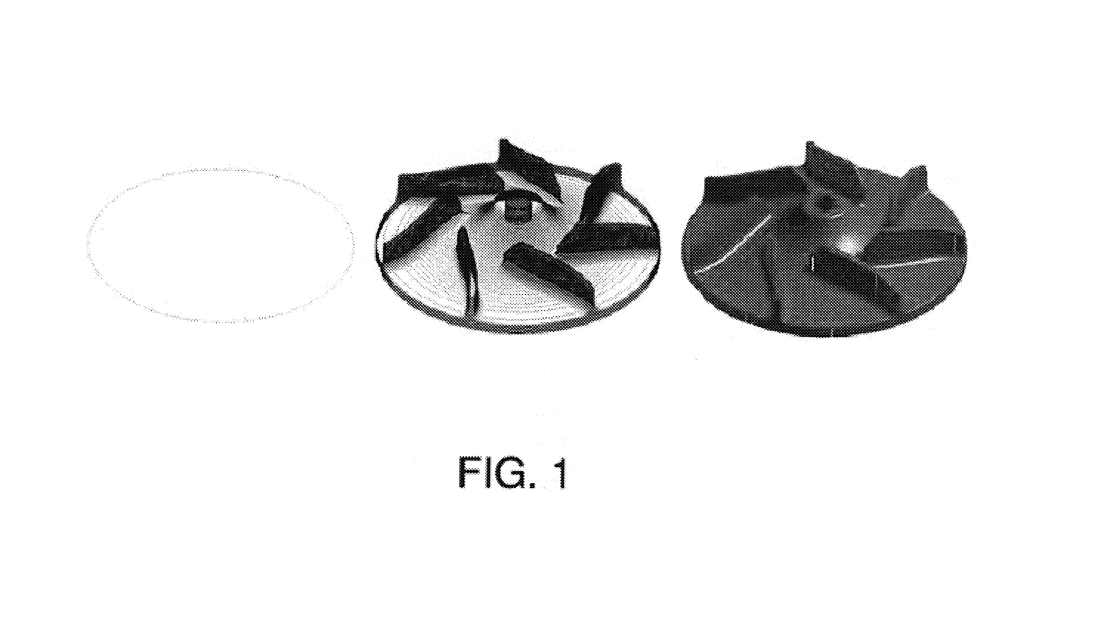
[0092]FIG. 14 is a photograph showing an impeller part manufactured by the laser-aided direct metal manufacturing technology of the present invention. The material of a substrate and a cladding was H-13 tool steel. The other conditions are the same as those of application 2. The laser shaping time required for manufacturing the mold was 12 hours and 8 minutes.


PUM

PropertyMeasurementUnit
thicknessaaaaaaaaaa
lengthaaaaaaaaaa
lengthaaaaaaaaaa

Abstract

The object of this invention is to provide a method and system for real-time monitoring and controlling the height of a deposit by using image photographing and image processing technology in a laser cladding and laser-aided direct metal manufacturing process. This invention also provides a method of controlling the intensity of laser power, which is one of the most important process variables, regardless of the operational condition of a laser power unit (401). The method and system of this invention controls the height of a deposit (205) by real-time monitoring the position and the height of a melt pool (203) and controlling the process variables using the image photographing and image processing technology in such a laser cladding and laser-aided direct metal manufacturing process based on a laser surface modification technology, such as laser surface alloying and laser cladding, or a laser-aided direct metal manufacturing technology.

Description

TECHNICAL FIELD [0001]The present invention relates to a method of real-time monitoring and controlling the height of a cladding layer using image photographing and image processing technology in laser cladding and direct metal manufacturing.BACKGROUND ART [0002]Laser-aided direct metal manufacturing is defined as rapid near-net shaping that can rapidly manufacture 3D products and tools necessary for the manufacture of the products with functional materials (for example, metal, alloy, ceramic or the like) on the basis of the digital data of 3D subjects stored in computers, and falls under “direct metal tooling”.[0003]The digital data of 3D subjects includes 3D Computer Aided Design (CAD) data, medical Computer Tomography (CT) and Magnetic Resonance Imaging (MRI) data, and digital data measured by 3D object digitizing systems, and the tools denote trial and mass-production molds and dies necessary for the manufacture of products.[0004]Those techniques allow functional metal prototype...

Claims


Application Information

Patent Timeline
Patent Type & Authority Patents(United States)
IPC IPC(8): B23K26/00B22D23/00B22C9/06B23K26/03B23K26/34G05B19/4099
CPCB23K26/032B23K26/34B23K26/3273B23K26/3206G05B19/4099G05B2219/45164B23K26/32B23K2103/50B23K2103/52B33Y50/02
Inventor SUH, JEONG-HUN
Owner INSSTEK
Why Eureka
Try Eureka