
Lithographic printing plate precursor and lithographic printing method

a technology of lithographic printing plate and precursor, which is applied in the direction of lithography, photosensitive materials, instruments, etc., can solve the problems of inability to use in image recording with infrared lasers, inability to use materials in infrared laser image recording, and inability to achieve image strength (adhesion with a support) extremely weak, so as to achieve good aging stability of colored image, and good visibility of printing plate

Active Publication Date: 2008-09-16
FUJIFILM CORP
View PDF21 Cites 49 Cited by
  • Summary
  • Abstract
  • Description
  • Claims
  • Application Information

AI Technical Summary

Benefits of technology

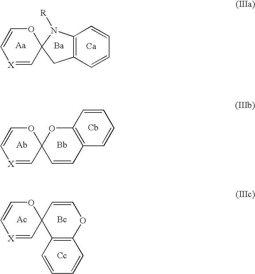
The invention provides a lithographic printing plate precursor with good visibility of a printing plate after exposure. This is achieved by using a spiropyran or spirooxazine compound and an acid generator capable of generating acid by the action of the spiropyran or spirooxazine compound. The invention also provides an on-press development type or non-development type lithographic printing plate precursor with good visibility of a printing plate after exposure. Additionally, the invention provides a lithographic printing method using the lithographic printing plate precursor. The use of a spiropyran or spirooxazine compound and an acid generator can also improve the aging stability of a colored image formed by exposure and enable plate detection before development.

Problems solved by technology

However, when a conventional image-recording layer of an image-recording system utilizing ultraviolet rays and visible rays is used, it is necessary to take methods requiring much labor, such that the exposed lithographic printing plate precursor must be stored under a completely light-shielding condition or a constant temperature condition until it is mounted on a printing press, since the image-recording layer is not fixed after exposure.
However, many conventional photosensitive materials useful as image-recording layers in practical use have photosensitive wavelengths in the visible ray region of 760 nm or less, so that these materials cannot be used in image recording with infrared lasers.
However, there is a problem that a method of forming an image by coalescence of fine particles by mere thermal fusion as above certainly shows a good on-press developing property, but image strength (the adhesion with a support) is extremely weak and press life is insufficient.
However, in a lithographic printing plate precursor of an on-press development type or a non-processing (non-development) type not accompanied by development process before printing, the discrimination of a plate cannot be done, since there is no image on the printing plate, which sometimes leads to the error in operation.
However, since an on-press development type lithographic printing plate precursor is subjected to no special process after exposure until development on a printing press, it is necessary that plate detection be done by colored or decolored images only by exposure operation.
Further, it is desired that a colored image is not decolored and stable due to the lapse of time.
However, these are techniques of systems that cause decoloration by exposure and not to obtain a colored image by exposure.
However, the patent is related to photography and copying materials using photo-chromic compounds, and on-press development type lithographic printing plate precursors using infrared lasers is not disclosed at all.

Method used


Image

  • Lithographic printing plate precursor and lithographic printing method
  • Lithographic printing plate precursor and lithographic printing method
  • Lithographic printing plate precursor and lithographic printing method

Examples


example

[0346]The invention will be described more specifically with referring to examples, but the invention is not limited thereto.

Manufacture of Support:

(1) Support A

[0347]For removing the rolling oil of the surface, an aluminum plate having a thickness of 0.3 mm (material 1050) was subjected to degreasing treatment with a 10 mass % sodium alminate aqueous solution at 50° C. for 30 seconds, and after degreasing the aluminum surface was subjected to brush-graining with three nylon brushes planted with hairs having a hair diameter of 0.3 mm and a suspension of pumice stone and water of a median diameter of 25 μm (the specific gravity: 1.1 g / cm3), and the surface of the plate was thoroughly washed with water. The plate was immersed in a 25 mass % sodium hydroxide aqueous solution at 45° C. for 9 seconds for etching, and then washed with water. After water washing, the plate was further immersed in a 20 mass % nitric acid aqueous solution for 20 seconds, followed by washing with water. The e...

example 11

[0362]The image-recording layer coating solution having the composition shown below was coated on support (a) with bar coating, dried at 100° C. for 60 seconds in an oven, whereby an image-recording layer having a dry coating weight of 1.0 g / m2 was formed, thus lithographic printing plate precursor (11) was obtained.

[0363]The image-recording layer coating solution was prepared by the mixture and stirring of the photosensitive liquid (11) and microcapsule liquid (2) shown below just before coating.

[0364]

Photosensitive liquid (11)Binder polymer (1) shown above0.147 gPolymerization initiator (1) shown above0.091 gInfrared absorber (1) shown above0.018 gPolymerizable compound0.350 gARONIX M-215 (manufactured byTOAGOSEI CO., LTD.)Fluorine surfactant (1) shown above0.040 gMethyl ethyl ketone0.991 g1-Methoxy-2-propanol7.816 gMicrocapsule liquid (2)Microcapsule dispersion (B)2.397 g(synthesized as shown below)Water2.202 g

Synthesis of Microcapsule Dispersion (B):

[0365]As the oil phase compon...

example 12

[0368]The image-recording layer coating solution having the composition shown below was coated on support (a) with bar coating, dried at 100° C. for 60 seconds in an oven, whereby an image-recording layer having a dry coating weight of 1.0 g / m2 was formed. An image-recording layer coating solution was prepared by the mixture and stirring of photosensitive liquid (12) shown below and microcapsule liquid (1) just before coating.

[0369]Further, protective layer coating solution (1) having the composition shown below was coated on the image-recording layer with bar coating, dried at 120° C. for 75 seconds in an oven, whereby a protective layer having a dry coating weight of 1.0 g / m2 was formed, thus lithographic printing plate precursor (12) was obtained.

[0370]

Photosensitive liquid (12)Binder polymer (1) shown above0.147 gPolymerization initiator (1) shown above0.091 gInfrared absorber (1) shown above0.018 gPolymerizable compound0.350 gARONIX M-215 (manufactured byTOAGOSEI CO., LTD.)Fluo...


PUM

PropertyMeasurementUnit
pKaaaaaaaaaaa
wavelengthaaaaaaaaaa
photosensitive wavelengthsaaaaaaaaaa

Abstract

A lithographic printing plate precursor comprising a support and an image-recording layer containing at least one compound selected from the group consisting of a spiropyran compound and a spirooxazine compound, and an acid generator, and a lithographic printing method including a process of removing the unexposed area of the image-recording layer on a printing press.

Description

BACKGROUND OF THE INVENTION[0001]1. Field of the Invention[0002]The present invention relates to a lithographic printing plate precursor having good visibility of a printing plate after exposure, and to a lithographic printing method including on-press development.[0003]2. Background Art[0004]A lithographic printing plate generally comprises a lipophilic image area that receives ink and a hydrophilic non-image area that receives a fountain solution in printing. Lithographic printing is a printing method of making difference in ink-adhering property on the surface of a lithographic printing plate with the lipophilic image area of the lithographic printing plate as the ink-receptive area and the hydrophilic non-image area as the fountain solution-receptive area (ink-repellent area) by making use of the natures of water and oily ink of repelling to each other, adhering ink only on the image area and transferring the ink to the material to be printed, e.g., paper.[0005]For manufacturing...

Claims


Application Information

Patent Timeline
Patent Type & Authority Patents(United States)
IPC IPC(8): G03F7/00G03F7/004
CPCB41C1/1008B41C1/1016B41C2201/02B41C2201/06B41C2210/24B41C2201/14B41C2210/04B41C2210/08B41C2210/22B41C2201/10
Inventor OSHIMA, YASUHITOOOHASHI, HIDEKAZUENDO, AKIHIRO
Owner FUJIFILM CORP
Learn More