Method and apparatus for measuring fluorescence polarization in lab-on-a-chip

a fluorescence polarization and lab-on-chip technology, applied in the field of lab-on-chip fluorescence polarization measurement system, can solve the problems of difficult to monitor the reaction of continuously flowing samples, difficult to collect a considerable amount of separated biomolecules for the large cuvette, and the high-throughput analysis system for measuring fluorescence polarization fp has not been well known. , to achieve the effect of enhancing the signal-to-noise ratio, reducing

Inactive Publication Date: 2008-09-23
KOREA INST OF SCI & TECH
View PDF7 Cites 2 Cited by
  • Summary
  • Abstract
  • Description
  • Claims
  • Application Information

AI Technical Summary

Benefits of technology

[0029]The lab-on-a-chip is made of glass by standard semiconductor photolithographic techniques and has a width and a length of 1 cm to 10 cm, respectively. The microchannel of the lab-on-a-chip has a depth of 5 μm to 150 μm, a width of 10 μm to 300 μm and a length of 10 mm to 100 mm. In the present invention, it is desirable to use a microchannel having a width of 10 μm to 100 μm. Here, the glass chip can provide successive injection measurements in high sensitivity since it has relatively less absorption problems.
[0051]The method for measuring fluorescence polarization FP, the detection method using the same and the method for measuring the activity or the concentration using the same in accordance with the present invention stores two substances for the measurement in reservoirs of a lab-on-a-chip to be injected into a microchannel by the pressure gradient generated using a vacuum pump, thus readily confirming the binding state of the substances and whether the substances induce or inhibit the formation of the complex. Accordingly, the methods described above may be applied usefully to the measurement of the substances that induce or inhibit the formation of the complex of biomolecules or the activity or the concentration of enzymes using the method for measuring fluorescence polarization FP.
[0072]The vertical fluorescence signal is measured by the vertical PMT and the horizontal fluorescence signal by the horizontal PMT. Ideally, two PMTs should receive 100% vertical and horizontal fluorescence signals. However, 1% vertical fluorescence signal is mixed in the signal received by the horizontal PMT, while >99% vertical fluorescence signal is received by the vertical PMT. Accordingly, another polarizer installed in front of the horizontal PMT minimizes the vertical component mixed with the signal and increases the horizontal fluorescence content.
[0073]In addition, an optical chopper composed of a slotted rotating disc is placed between the first filter and the first mirror for turning on / off the light source periodically, which improves the signal-to-noise ratio, thus allowing the measurement of fluorescence polarization using minute amounts of samples possible in the narrow microchannel of the present invention.
[0076]Furthermore, this invention allows cost reduction in analysis, when compared to a high-throughput analysis using a 384-well plate which requires about 4 pmol per sample.
[0077]Accordingly, the method and apparatus for measuring fluorescence polarization of the present invention configured to enhance the signal-to-noise ratio to increase sensitivity and reliability of measurements can readily measure interactions between biomolecules efficiently at low cost with a minute amount of samples, and be applied to an ultra-speed measurement aimed at such advantages.

Problems solved by technology

Since the system described above comprises two steps of separating and measuring and uses a relatively large cuvette cell (0.2 mm×0.2 mm), it has a drawback in collecting a considerable amount of separated biomolecules for the large cuvette cell [Anal. Chem. 72(2000) pp.
In addition, the use of the disposable plastic channel has some drawbacks in that it is difficult to monitor the reaction of continuously flowing samples, and to measure the fluorescence signals due to large background signals in a miniaturized microchannel.
However, a high-throughput analysis system for measuring fluorescence polarization FP in a lab-on-a-chip has not been well known.
But the method has a problem in that it needs specific substrates for the respective proteases.

Method used


Image

  • Method and apparatus for measuring fluorescence polarization in lab-on-a-chip
  • Method and apparatus for measuring fluorescence polarization in lab-on-a-chip
  • Method and apparatus for measuring fluorescence polarization in lab-on-a-chip

Examples


embodiment 1

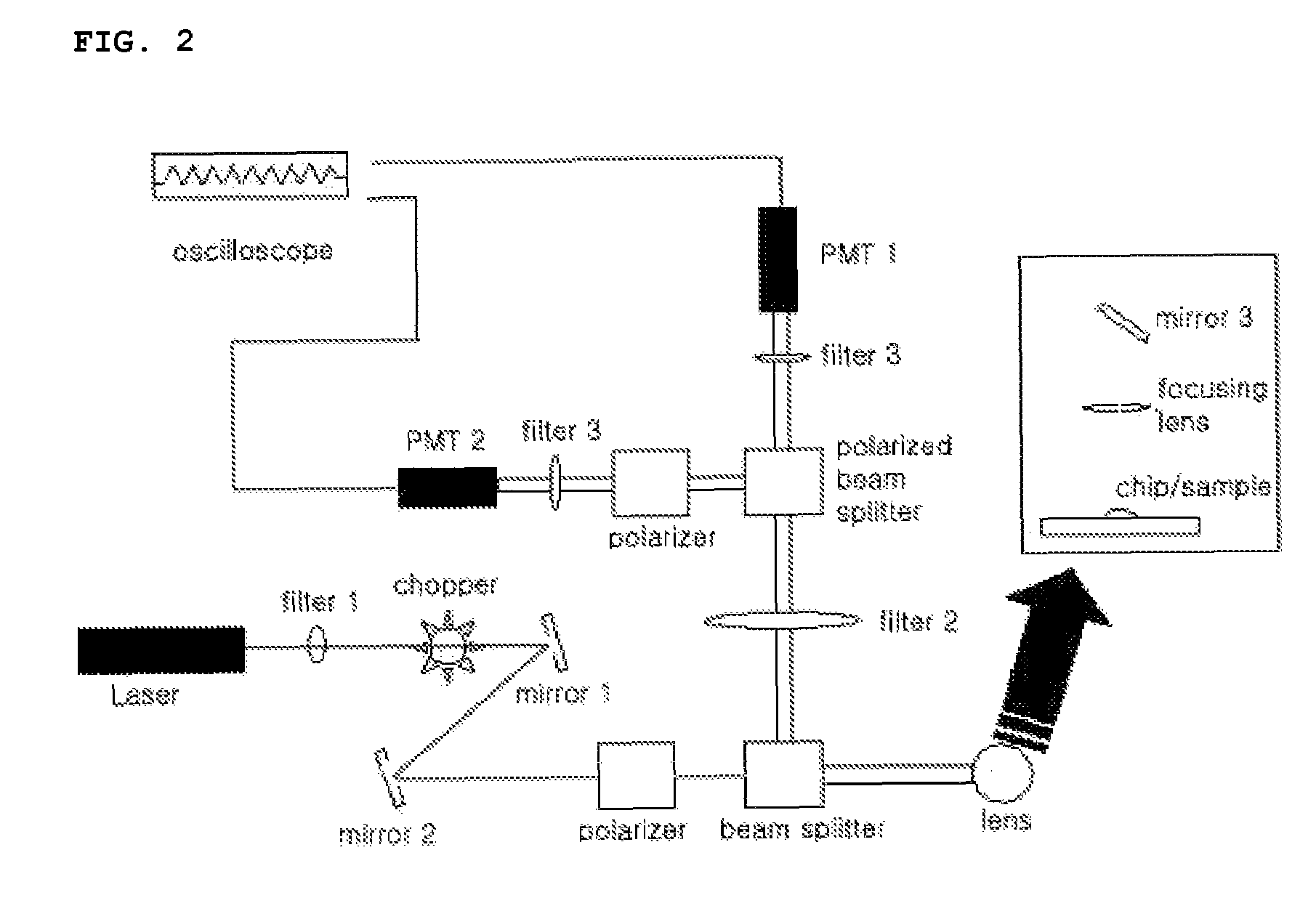
[0093]Fluorescence polarization FP for the complex formation of biotin and streptavidin was measured in a 100 μL cuvette using an apparatus for measuring fluorescence polarization FP of FIG. 2, wherein an optical chopper was not inserted.

[0094]In this Embodiment, the measurements were carried out, and separately divided into three cases according to the respective samples used for the complex formation of biomolecule-fluorescently labeled biomaterial as follows (FIG. 5): (A) and (B), wherein only 1.25 μM of TMR was put therein; (C) and (D), wherein 1.25 μM of TMR-biotin was put therein; and (E) and (F), wherein 10 μM of TMR-biotin and 2.5 μM of streptavidin were put therein.

[0095]First, 100 nM of TMR used as a fluorescent probe for fluorescently labeled biomaterials was filled in the 100 μL cuvette of the lab-on-a-chip with the fluorescence polarization detection setup in FIG. 2, in which a polarizer was detached, and laser beam was irradiated to induce fluorescence. Then, the fluor...

embodiment 2

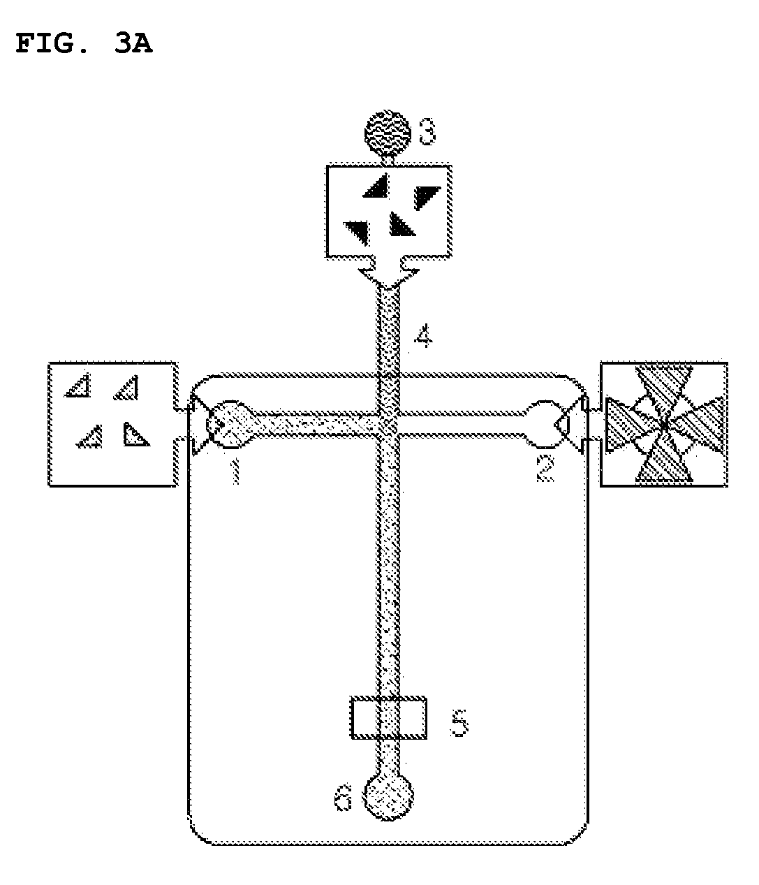
[0116]Fluorescence polarization FP for the complex of biotin and streptavidin in a lab-on-a-chip was measured using the apparatus of FIG. 2, wherein the optical chopper was not inserted. In this Embodiment, a lab-on-a-chip made of glass and composed of a microchannel having a depth of 12 μm and a width of 79 um was used instead of the 100 μL cuvette. After filling 100 μM of tetramethylrhodamine TMR solution in the microchannel of the lab-on-a-chip using a vacuum pump, a G-factor value was obtained in the same manner described above in Embodiment 1. Then, for the measurement, the samples were filled in reservoirs 1 and 2 of the lab-on-a-chip as depicted in FIG. 3A as following three cases: (A) wherein 1.25 μM of tetramethylrhodamine TMR was filled in the reservoir 1; (B) wherein 1.25 μM of TMR-biotin was put into the reservoir 1; and (C, D and E) wherein 10 μM of TMR-biotin and 2.5 μM of streptavidin were filled, respectively, in the reservoirs 1 and 2. Subsequently, the above sample...

embodiment 3

[0120]Fluorescence polarization for the complex of biotin and streptavidin was measured using the apparatus of FIG. 2 including the optical chopper of the invention. In this Embodiment, a lab-on-a-chip made of glass and composed of a microchannel having a depth of 12 μm and a width of 79 μm was used to measure fluorescence polarization for a complex of biomolecule-fluorescently labeled biomaterial.

[0121]For the measurement, the samples were respectively filled in the reservoir of the lab-on-a-chip as following three cases: (A) wherein 4 μM of tetramethylrhodamine TMR was filled in the reservoir; (B) wherein 4 μM of TMR-biotin was put into the reservoir; and (C) wherein 4 μM of TMR-biotin and 1 μM of streptavidin were filled in the reservoirs.

[0122]Fluorescence polarizations FP for the above samples were measured in the microchannel of the lab-on-a-chip using the apparatus of FIG. 2 including the optical chopper.

[0123]As a result, in case of (A), fluorescence polarization was measure...


PUM

PropertyMeasurementUnit
widthaaaaaaaaaa
diameteraaaaaaaaaa
volumeaaaaaaaaaa

Abstract

Disclosed relates to a method and an apparatus for measuring fluorescence polarization FP in a lab-on-a-chip and, more concretely, to a method and an apparatus that measure quantitatively interactions between biomolecules and fluorescently labeled biomaterials and enzyme activities using the measurement of fluorescence polarization FP. The method and the apparatus of the invention provide rapid assays with minute amounts of samples using an automated device compared to conventional methods. Accordingly, the method and the apparatus of the invention can be usefully applied to the measurement of interactions between biomolecules and to the protease assays using a protein substrate.

Description

BACKGROUND OF THE INVENTION[0001]1. Field of the Invention[0002]The present invention relates to a fluorescence polarization measurement system in a lab-on-a-chip and, more particularly, to a method and an apparatus for measuring fluorescence polarization FP in a lab-on-a-chip that analyze quantitatively interactions between minute amounts of biomolecules using fluorescence polarization, and a method for detecting a substance that induces or inhibits formation of a complex of biomolecules using the method for measuring fluorescence polarization in a lab-on-chip.[0003]2. Description of Related Art[0004]A fluorometry that measures fluorescence provides one of the important methods in bioassay techniques. The fluorometry includes fluorescence intensity, fluorescence fluctuation spectroscopy, fluorescence imaging, fluorescence resonance energy transfer (FRET), and fluorescence polarization FP. Due to its sensitive nature, the fluorometry has been continuously substituted for assay metho...

Claims


Application Information

Patent Timeline
Patent Type & Authority Patents(United States)
IPC IPC(8): G01N21/76
CPCG01N21/6445G01N33/542G01N21/6428B01L3/5027G01N21/05G01N21/6408G01N2021/0346
Inventor YANG, EUN GYEONGKIM, JUNG HWANKIM, TAE SONGJU, BYEONG-KWONKANG, JI YOONSHIN, HYUN JOONCHO, HAN-SANG
Owner KOREA INST OF SCI & TECH
Why Eureka
Try Eureka