Fluid borne particle analyzers

a technology of fluid borne particles and analyzers, which is applied in the direction of fluorescence/phosphorescence, optical radiation measurement, instruments, etc., can solve the problems of contaminating industrial products and processes, so as to maximize the opportunity, enhance the sensitivity, and minimize the effect of affecting the sensitivity of the apparatus

Active Publication Date: 2008-10-14
THE SEC OF STATE FOR DEFENCE IN HER BRITANNIC MAJESTYS GOVERNMENT OF THE UK OF GREAT BRITAIN & NORTHERN IRELAND
View PDF14 Cites 27 Cited by
  • Summary
  • Abstract
  • Description
  • Claims
  • Application Information

AI Technical Summary

Benefits of technology

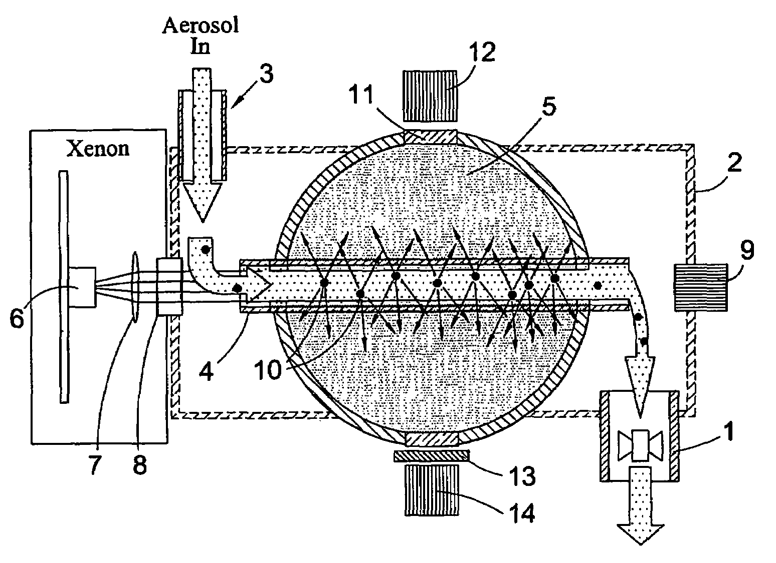
[0033]The provision of an integrating sphere within which the test aerosol flows and is illuminated dramatically enhances sensitivity. The integrating sphere not only allows a proportionally larger scattering volume to be implemented, therefore retaining detection sensitivity even for low particle concentrations, but also acts as a very efficient collector of scattered and fluorescence radiation emanating from any airborne particles under examination, thus maximising the opportunity for using a combination of scatter and fluorescence signals in discriminating the types of particles present in the aerosol.
[0034]Particularly preferably the apparatus is configured so that the fluid to be analyzed flows through the integrating sphere along a flow path and the illumination / irradiation source is directed along the flow path whereby the illuminations / irradiation and the fluid enter the integrating sphere by a common aperture. By the use of at least a common entry aperture into the integrating sphere for both the fluid and the illumination / irradiation the number / area of apertures that would otherwise undermine the sensitivity of the apparatus is minimized.
[0037]Where the illumination / irradiation is directed along the tube as a beam, the diameter of the beam is advantageously such that the beam fills most of the tube without coming into contact with the tube walls, thus avoiding scattering from particles that may have deposited on the walls.
[0047]In a further aspect of the present invention there is provided a method for the detection of fluid borne particles comprising the provision of an apparatus substantially of the first or second aspects of the present invention with or without an integrating sphere or spherical mirrors and wherein the method comprises alternately illuminating a said zone with different wavelength bandwidths of light to elicit different wavelengths of fluorescent radiation from any biological particles in said zone and monitoring for the different bandwidth wavelengths of fluorescence elicited and obtaining a ratio of the sensed signal for wavelength or wavelength band of illuminating light relative to a corresponding signal for another wavelength or wavelength band of illuminating light as a means of facilitating characterizing of any biological particles within the zone.

Problems solved by technology

Environmental airborne particles, usually comprising mineral dusts, combustion products and biological particles, which are carried by winds and other air movement, can result in breathing difficulties, allergic reactions a possible degradation of the body's immune system.
Occupational particles can contaminate industrial products and processes and can also present a respirable health hazard, such as in the case of asbestos fibres or fugitive pharmaceutical powder particles.
In the military field, the deliberate generation of hazardous aerosols has posed a major threat since their first substantial use in World War I, and today a wide variety of biological and chemical weapons are believed to be possessed by both national governments and terrorist organisations.
Moreover, since even brief exposure to some of the aforementioned aerosols can damage health and may even prove fatal, the speed of response of the measurement technique has been an important consideration.
Such methods offer a high degree of particle discrimination but remain expensive and cumbersome to implement and, because they are comparatively slow in terms of the rate at which individual particles can be analyzed, they do not offer the real-time aerosol analysis capability (ie: response to a change in aerosol composition within a few seconds) desired in monitoring applications.
Whilst comparatively straightforward to implement, simple light scattering techniques such as these do not yield sufficient information about the particles to provide anything other than a very superficial overview of the ambient aerosol.
However, light scattering analysis instruments of the type described above cannot discriminate particles on the basis of their material structure.
However, all of the methods described above involve the analysis of individual particles at normally high processing rates.
Whilst offering a high degree of particle discrimination, the methods all suffer the same problem of being expensive and complex to implement.
This high cost is a result of the requirement for an intense and well-collimated light source, usually a laser, the requirement for precision optical systems, the need for complex and high-speed data processing electronics, and, normally, the need for an independent power generator to supply the instruments with electrical power over extended time periods.
Because of the high cost of implementing the methods, the deployment of monitors based on them is normally limited to very small numbers of discrete monitors.
In some cases, especially outdoor environments or areas of military conflict, the biological threat may appear anywhere across a large area, and the deployment of small number of discrete monitors is of limited value in rapidly detecting the threat, should it arise.
A potential drawback of this type of detector relates to the size of the volume of the illuminated air parcel (referred to as the ‘scattering volume’).
Equally, if only a small number of particles is present in the scattering volume, the magnitude of the recorded scatter and fluorescence light signals may be too low for accurate measurement, primarily because the scatter and fluorescent light emanates from the particles in all directions and yet is collected over only a small fraction (typically ˜10% of the total).

Method used


Image

  • Fluid borne particle analyzers
  • Fluid borne particle analyzers
  • Fluid borne particle analyzers

Examples


second embodiment

[0055]In the invention, the optical filter 8 is replaced by a set of filters supported in, for example, a rotating filter-wheel, such that successive pulses of radiation from the xenon source 6 are filtered to transmit a succession of different wavelength bands. If, for example, the filter wheel held three filters, then the xenon would be triggered to produce three pulses in rapid succession, followed by a gap of ˜0.5 seconds. Thus the particles suspended within the quartz tube 4 would sequentially be illuminated at three different wavelength bands, and the outputs recorded from the fluorescence detector 14 would reflect the degree to which specific biological fluorophores such as Tryptophan or NADH were present. This information would significantly enhance the ability of the invention to discriminate various types of biological particles in the air.

third embodiment

[0056]In the invention, the number of ‘fluorescence detector’ windows 12 could be increase to typically three or four, with each having a different optical filter. In this way, the spectral distribution of fluorescence radiation emanating from the illuminated particles could be measured. This would further enhance the ability of the invention to discriminate various types of biological particles in the air. (A drawback of implementing additional windows in the integrating sphere is that the ‘sphere multiplier’ will decrease, thus reducing the ‘optical gain’ of the sphere and reducing overall sensitivity to low particle fluxes).

fourth embodiment

[0057]In the invention, the fluorescence detector 14 and its associated optical filter 13 are replaced by a spectrometer capable of providing an output representative of the spectral distribution of fluorescent light emanating from the particles. Again, this would increase discrimination of biological particles in the air, but at the cost of additional complexity and manufacturing cost.

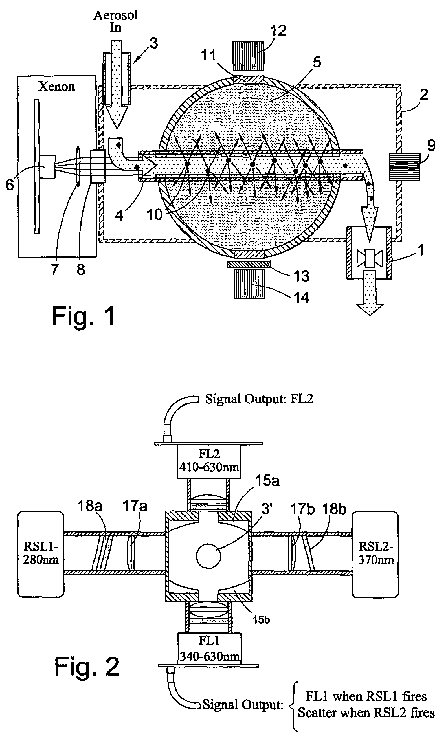
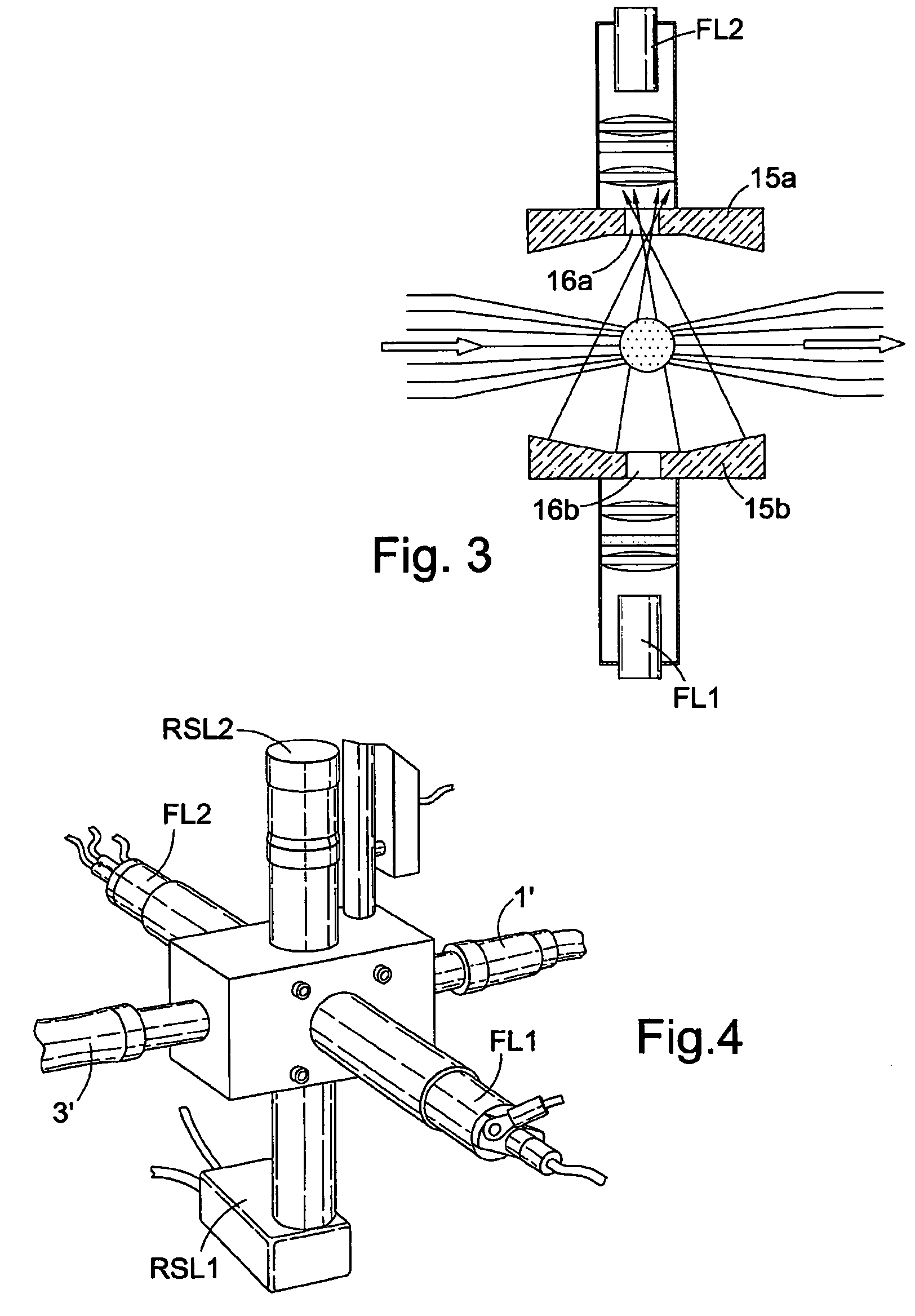
[0058]Turning now to FIGS. 2 to 4, these show a simplified low-cost bio-aerosol fluorescence sensor designed for unattended deployment in medium to large area networks surrounding vulnerable military or civilian sites. The sensor uses as the illumination source two compact xenon flash units RSL1, RSL2 to excite fluorescence in an aerosol sample volume of ˜5 ml. The aerosol is drawn from the ambient environment in through inlet pipe 3′ and out via outlet pipe 1′ at a flow rate of 10 litres min−1

[0059]A standard COTS absorption filter 18a restricts the excitation radiation from first xenon RSL1 to the U...


PUM

PropertyMeasurementUnit
wavelength bandaaaaaaaaaa

Abstract

This invention describes an improved method and apparatus for the analysis of fluid borne particles and which is especially suitable for the detection of airborne biological particles. In one aspect of the invention provides an apparatus for the detection of fluid borne particles which comprises a zone through which a fluid to be analyzed flows in use, a source of illumination to illuminate / irradiate fluid borne particles present in said zone, and a detector to detect light from the particles as an indicator of the presence or characteristics of the particles, wherein the apparatus comprises an integrating sphere and the zone is within the integrating sphere. The apparatus is highly sensitive and can be used for detecting airborne particles even where the particles are present at very low particle concentrations in the air.

Description

FIELD OF THE INVENTION[0001]The present invention concerns improvements in and relating to analyzers for fluid borne particles, e.g. analyzers for detecting or determining characteristics of biological particles such as bacterial cells present in a sample of air.BACKGROUND TO THE INVENTION[0002]In a wide variety of environmental, occupational, military and industrial scenarios, fine particles, typically within the size range from a few tenths of a micrometer to a few hundred micrometers, play an important role. Environmental airborne particles, usually comprising mineral dusts, combustion products and biological particles, which are carried by winds and other air movement, can result in breathing difficulties, allergic reactions a possible degradation of the body's immune system. Occupational particles can contaminate industrial products and processes and can also present a respirable health hazard, such as in the case of asbestos fibres or fugitive pharmaceutical powder particles. ...

Claims


Application Information

Patent Timeline
Patent Type & Authority Patents(United States)
IPC IPC(8): G01N21/00G01J1/04G01J1/42G01J3/44G01N1/24G01N15/02G01N21/05G01N21/53G01N21/64
CPCG01J3/4406G01N1/24G01N15/0211G01N21/05G01N21/53G01N21/645G01N21/6486G01N2021/6467G01N2201/065G01J1/04G01J1/4228
Inventor KAYE, PAUL HENRYHIRST, EDWIN
Owner THE SEC OF STATE FOR DEFENCE IN HER BRITANNIC MAJESTYS GOVERNMENT OF THE UK OF GREAT BRITAIN & NORTHERN IRELAND
Why Eureka
Try Eureka