
Ammonia oxidation and pipe denitrification

a technology of ammonia oxidation and denitrification pipe, which is applied in the field of waste treatment systems, can solve the problems that denitrification cannot proceed without a supplemental carbon source, and the recycle stream typically does not contain the requisite carbon,

Inactive Publication Date: 2008-10-21
PEDROS PHILIP B +1
View PDF7 Cites 21 Cited by
  • Summary
  • Abstract
  • Description
  • Claims
  • Application Information

AI Technical Summary

Benefits of technology

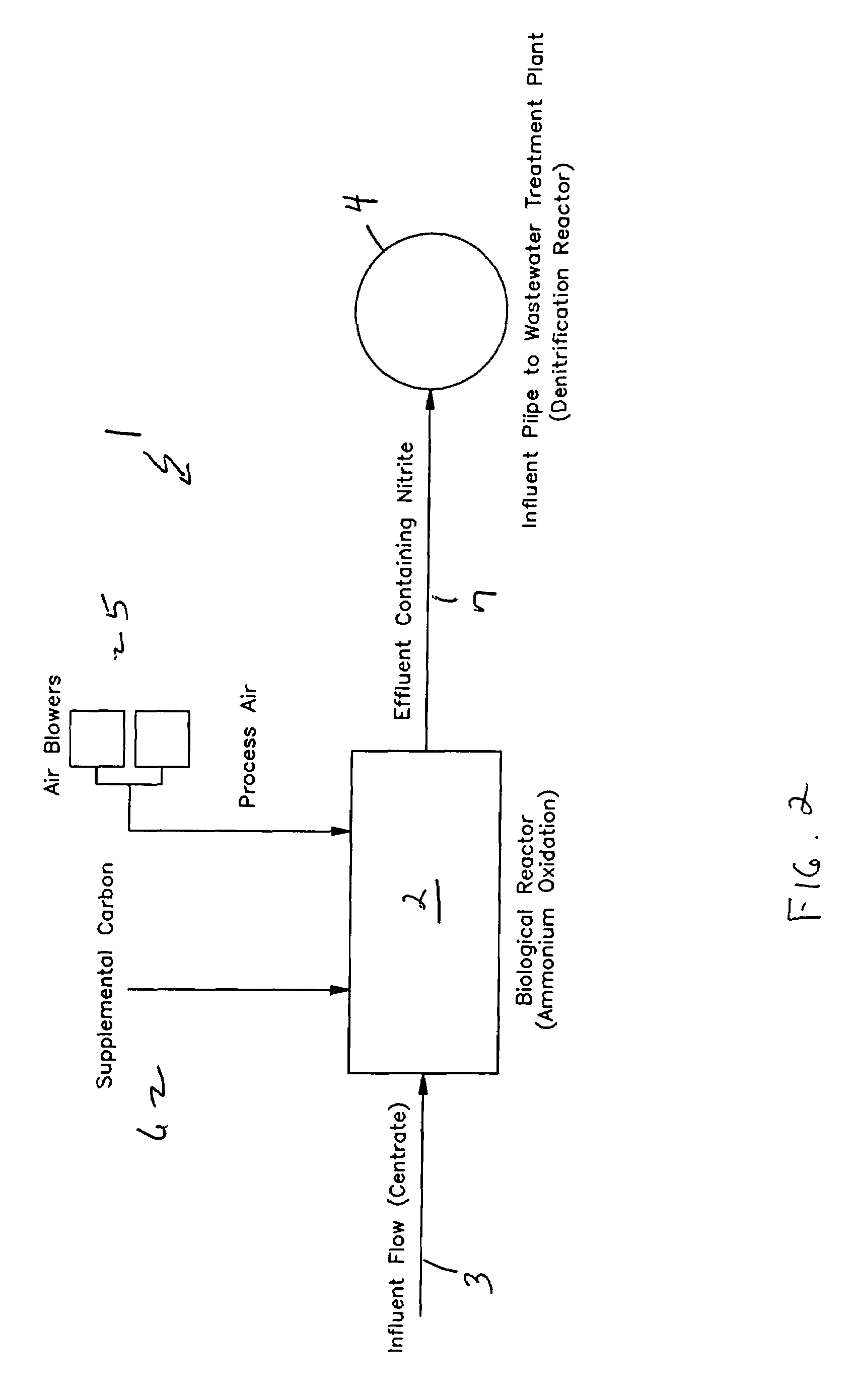
[0009]This process is designed to achieve complete nitrogen removal from a high ammonium concentration waste stream while minimizing both the quantity of air and the quantity of supplemental organic carbon required. This is achieved by using an intermittently aerated bioreactor to accomplish ammonium oxidation to nitrite (i.e. achieve only the first reaction in step one), and then to achieve denitrification by introducing the effluent from the bioreactor into the influent collection system or the headworks of the wastewater treatment plant. Denitrification will occur in the collection pipe using the influent organics as a carbon source. Typically, the wastewater recycle stream generated from the dewatering process from an anaerobicly digested of sludge contains concentrations of nitrogen in the range of 500-1,500 mg / l and alkalinity in the range of 2,000-4,000 mg / l; however, the concentrations of carbonaceous matter are relatively low and in the range of 150-600 mg / l. The pH may range from 7-9. To maintain the oxidation of ammonia to nitrite a supplemental alkalinity source is required to maintain the pH and necessary alkalinity demand of the AOB.
[0017]The process offers several advantages over a conventional biological nitrogen removal process. First, nitrogen removal via the nitrite route requires 25% less oxygen. Second, no supplemental carbon source is required since denitrification occurs within the pipe. Third, pipe denitrification reduces the carbonaceous load to the treatment plant. Fourth, addition of nitrite to the collection system may suppress odor production.

Problems solved by technology

In addition, this recycle stream typically does not contain the requisite carbon to nitrogen ratio (C / N) for nitrogen removal.
However, typically, the centrate from the dewatering process does not contain a large quantity of organics and therefore the criterion to achieve nitrification is readily established.
However, the low carbon to nitrogen ratio (C / N) resulting from the lack of organics means that denitrification will not proceed without a supplemental carbon source.

Method used


Image

  • Ammonia oxidation and pipe denitrification
  • Ammonia oxidation and pipe denitrification
  • Ammonia oxidation and pipe denitrification

Examples


Embodiment Construction

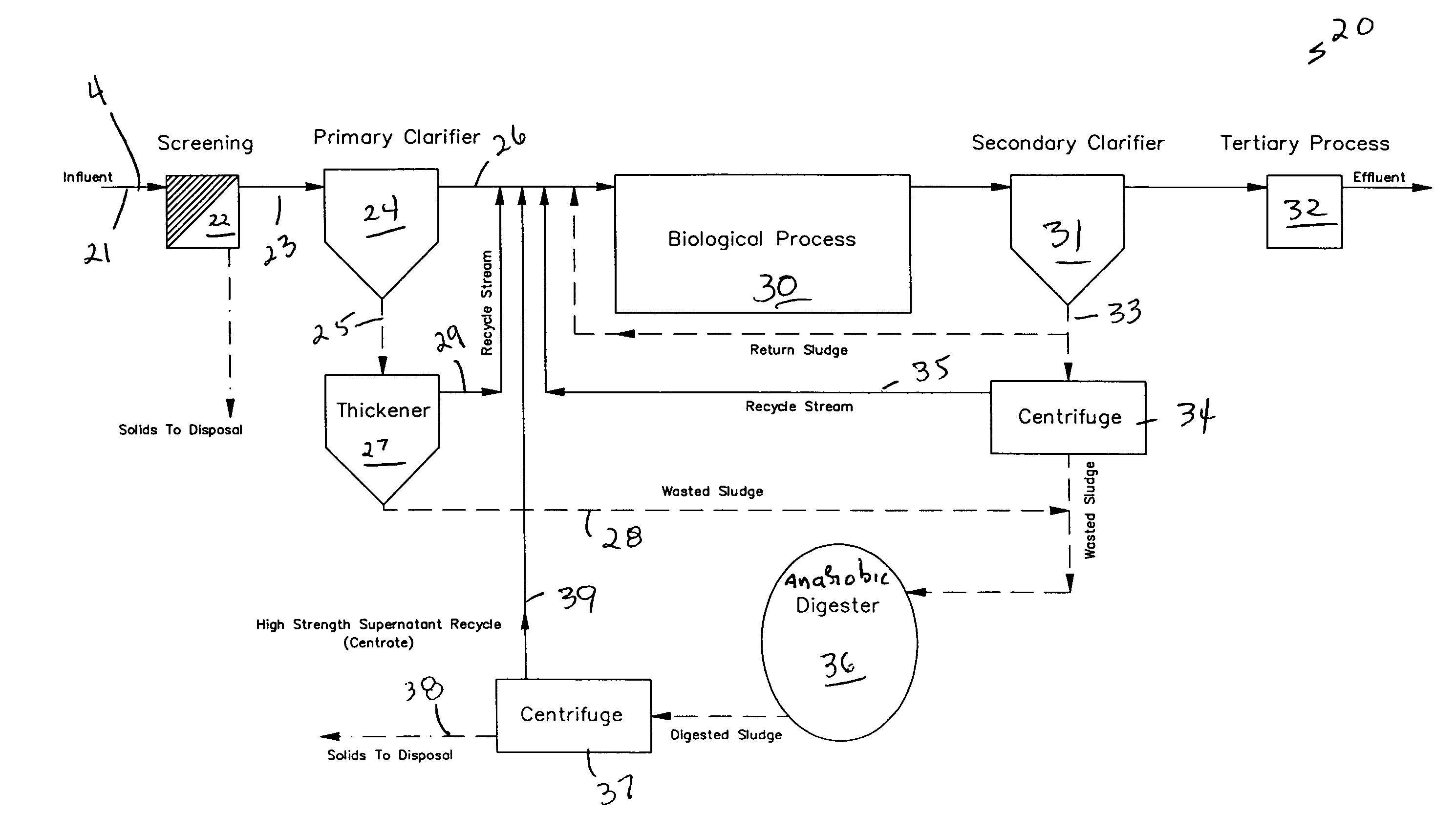
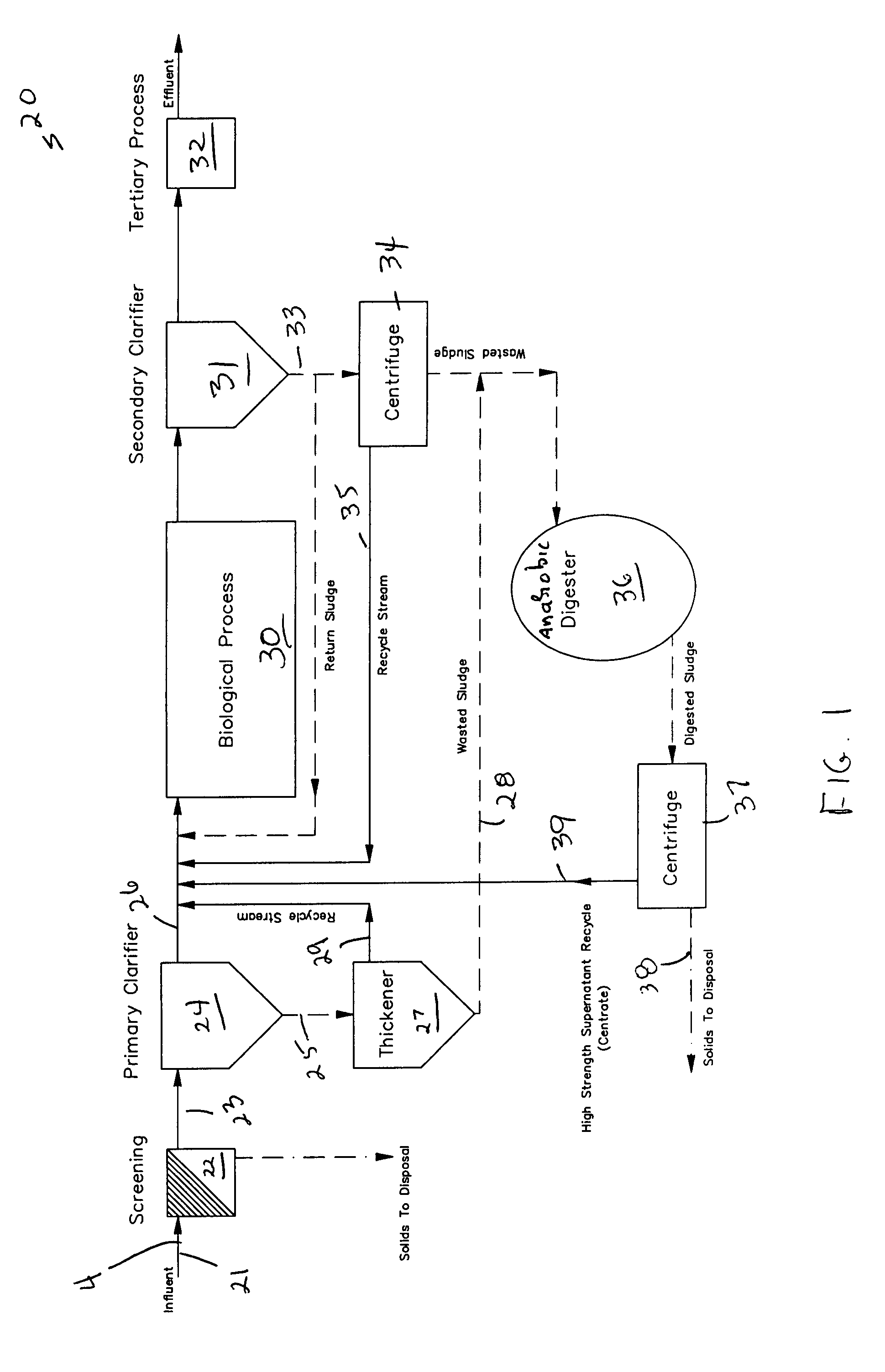
[0022]Referring to the drawings in detail wherein like elements are indicated by like numerals, there are shown a process flow for a typical wastewater treatment plant, and the invention process installed in the wastewater treatment plant 20.

[0023]Referring more particularly to FIG. 1, a typical wastewater treatment plant 20 will have a raw influent 21 passed to the plant 20 through an influent pipe 4. Solids within the raw influent will be filtered out through a screening assembly 22 and passed out for disposal. The screened raw influent 23 is then passed to a primary clarifier 24 where solids still within the screened raw influent will separate into a sludge component 25 and a liquid component 26. The sludge component 25 is passed to a thickener 27 with the wasted sludge 28 then passed to a digester 36. The clarifier liquid component 26 and thickener liquid component 29 are then brought into the treatment plant's main biological processor 30. The biological processor output is the...


PUM

PropertyMeasurementUnit
concentrationsaaaaaaaaaa

Abstract

In a biological wastewater treatment system, the addition of an intermittently aerated second bioreactor to accomplish ammonium oxidation to predominately nitrite and then to achieve denitrification by introducing the effluent, containing nitrite, from the second bioreactor into the influent collection system or the head works of a wastewater treatment plant. Denitrification from nitrite occurs in the collection pipe using the influent organics as a carbon source.

Description

CROSS-REFERENCE TO RELATED APPLICATIONS[0001]Applicant claims the priority benefits of U.S. Provisional Patent Application No. 60 / 791,729 filed Apr. 13, 2006.BACKGROUND OF THE INVENTION[0002]This invention relates to waste treatment systems, and in particular, to a method for removing ammonia content from waste streams with a high ammonium-nitrogen concentration.[0003]The supernatant from the anaerobic digestion of blended or secondary sludge contains high concentrations of ammonium that as a recycle stream to the influent of a wastewater treatment plant may account for as much as 25% of the nitrogen loading to the plant. In addition, this recycle stream typically does not contain the requisite carbon to nitrogen ratio (C / N) for nitrogen removal. However, removal of the nitrogen prior to reentering the treatment plant would reduce the main treatment plant's downstream nitrification and denitrification requirements and may provide additional options for treatment plant upgrades.[0004...

Claims


Application Information

Patent Timeline
Patent Type & Authority Patents(United States)
IPC IPC(8): C02F3/00
CPCC02F3/1221C02F3/302C02F11/04Y02W10/10
Inventor PEDROS, PHILIP B.DOBIE, KEITH
Owner PEDROS PHILIP B
Learn More