Laser marking of raw aluminum anode foil to induce uniform patterning etching

a technology of laser marking and raw aluminum anode foil, which is applied in the direction of capacitor manufacture, variable capacitor, fixed capacitor, etc., can solve the problems of difficult packaging of implantable devices in small packages, patient's pectoral region, and inability to achieve uniform patterning etching, optimum tunnel distribution, and high capacitance

Inactive Publication Date: 2008-11-18
PACESETTER INC
View PDF25 Cites 22 Cited by
  • Summary
  • Abstract
  • Description
  • Claims
  • Application Information

AI Technical Summary

Benefits of technology

[0015]The laser marking of the foil allows for positional control of tunnel initiation. By controlling the position of tunnel initiation, foils are etched more uniformly and have optimum tunnel distributions, this allows for the production of highly etched foils that maintain high strength and have high capacitance. The present invention further includes an electrolytic capacitor comprising etched aluminum anode foils, which have been prepared using the methods of the present invention, and an ICD with the electrolytic capacitor comprising anode foils etched according to the present invention.

Problems solved by technology

Since these capacitors must typically store approximately 30-40 joules, their size can be relatively large, and it is difficult to package them in a small implantable device.
A patient who has a device implanted may often be bothered by the presence of the large object in his or her pectoral region.
Furthermore, the generally rectangular shape can in some instances lead to pocket erosion at the somewhat curved corners of the device.
The size and configuration of the capacitors has been a major stumbling block in achieving this goal.
However, high gain etching of valve metals for use as anodes in electrolytic capacitors tend to produce very brittle anode foil.
Typically the higher the gain of the anode foil, the more brittle the foil.
Accordingly, the capacitance and thereby the energy density are limited by the brittleness of the formed foil.
As the brittleness of the formed foil increases, cracks formed in the foil more easily propagate across the foil, resulting in broken anodes.

Method used


Image

  • Laser marking of raw aluminum anode foil to induce uniform patterning etching
  • Laser marking of raw aluminum anode foil to induce uniform patterning etching
  • Laser marking of raw aluminum anode foil to induce uniform patterning etching

Examples


example 1

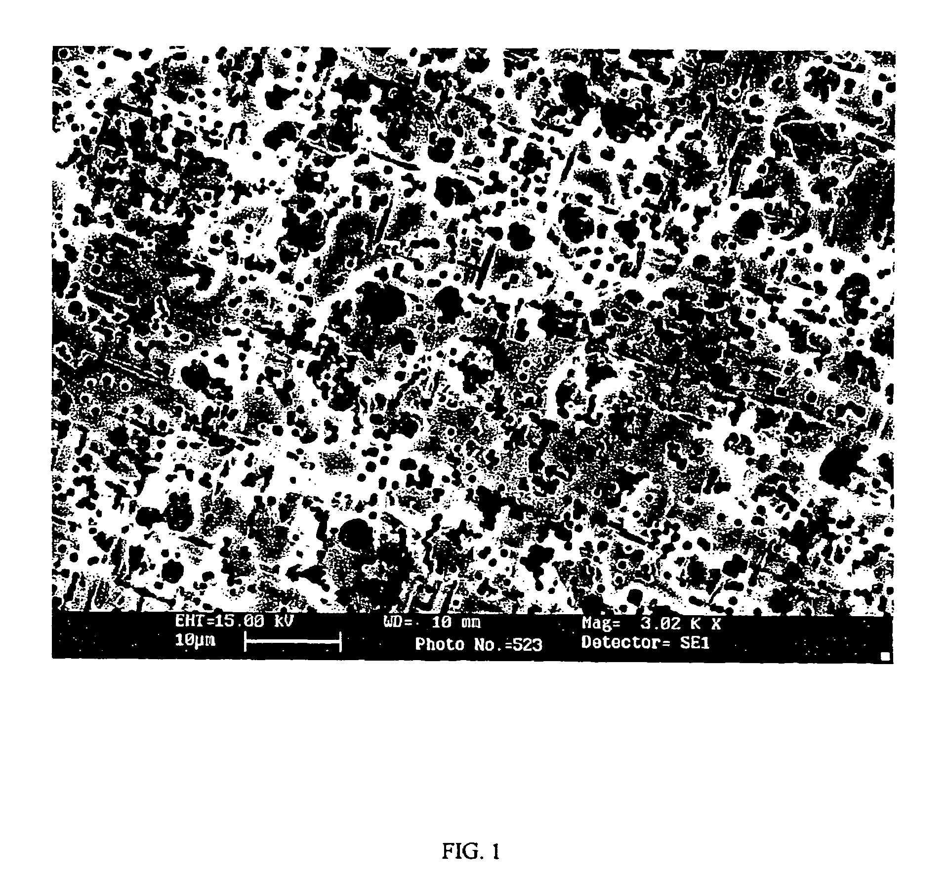
[0058]A laser was applied to an aluminum foil comprising about 97% high cubicity recrystallized aluminum to create a pattern of marks. A Nd:YAG laser was used to mark the foil. FIG. 6 shows a SEM picture of the resulting foil with the laser marks on the foil. As can be seen in the image, the marks are approximately circular dots. The dots also appear to be pits with elevated edges. This confirms the mark structure shown in FIG. 4.

example 2

[0059]In this example, a portion of a foil, similar to that of Example 1, was marked using a laser as in Example 1. The marked foil was electrochemically etched in aqueous anode electrolyte comprising about 500 PPM sulfate, about 2.6% sodium perchlorate, about 1.3% sodium chloride, and about 20% glycerol, at a temperature of about 80° C. The current density was about 0.15 amps / cm2. FIG. 7 shows a SEM picture of the laser marked foil after etching. In the portion where the laser was applied to create marks, the tunnel initiation is concentrated near the edges of the marks. In the unmarked portion, the tunnel initiation is concentrated near the rolling lines. This example shows that the laser marked spots facilitate etching more strongly than the rolling lines. This is clear evidence that the marks allow for precise positional control of tunnel initiation.

example 3

[0060]In this example, a regular pattern of marks was applied to an aluminum foil comprising about 97% high cubicity recrystallized aluminum. A Nd:YAG laser was used to mark the foil. The same marking conditions were used as in Example 1, however, the laser marking of the foil was performed under an Argon atmosphere. The Argon environment was used to reduce the amount of thermal oxide grown on the foil during the marking process. The chamber for laser marking the foil was purged with Argon for about 80 minutes before marking. After the laser marking process, the foil was etched in the sulfate etch solution and using the conditions described in Example 2. FIG. 8 shows a SEM picture of the etched foil marked under Argon. The tunnel initiation is still concentrated near the laser mark edge, as in Example 2. FIG. 9 shows a SEM picture of the same etched foil, with one mark magnified, which clearly shows tunnel initiation near the edge of the mark, with little tunnel initiation in the la...


PUM

PropertyMeasurementUnit
diameteraaaaaaaaaa
diameteraaaaaaaaaa
thickaaaaaaaaaa

Abstract

A method of producing a highly etched electrode for a capacitor from a foil is disclosed. The method comprises first applying a laser beam to the foil to form a plurality of marks on the foil surface and then etching the foil. Preferably, the laser marks facilitate etching of foil surface in areas near the marks and retard etching of foil surface inside the marks. After etching, the foil is further processed in a combination of optional steps such as forming and finishing steps. The laser marking of the foil allows for positional control of tunnel initiation, such that tunnel initiation density and the location of tunnel initiation is controlled. By controlling the position of tunnel initiation, foils are etched more uniformly and have optimum tunnel distributions, thus allows for the production of highly etched foils that maintain high strength and have high capacitance. The present invention further includes an electrolytic capacitor comprising etched aluminum anode foils, which have been prepared using the methods of the present invention.

Description

PRIORITY CLAIM[0001]This application is a continuation-in-part of U.S. patent application Ser. No. 10 / 680,777 filed Oct. 6, 2003 now abandoned and is incorporated herein by referenced.BACKGROUND OF THE INVENTION[0002]1. Field of the Invention[0003]The present invention is directed to a method of producing an electrode for use in the manufacture of electrolytic capacitors and more particularly to a method of creating porous electrode foil for use in multiple electrode stack configuration electrolytic capacitors of the type used in implantable cardioverter defibrillators (ICDs).[0004]2. Related Art[0005]Compact, high voltage capacitors are utilized as energy storage reservoirs in many applications, including implantable medical devices. These capacitors are required to have a high energy density since it is desirable to minimize the overall size of the implanted device. This is particularly true of an implantable cardioverter defibrillator (ICD), also referred to as an implantable def...

Claims


Application Information

Patent Timeline
Patent Type & Authority Patents(United States)
IPC IPC(8): H01G4/00C23F1/00C23F3/00
CPCC23F1/02C23F4/00C25F3/02C25F3/04H01G9/045H01G9/055
Inventor HEMPHILL, R. JASONJIANG, XIAOFEISTOCKER, TEARLTHOMPSON, GARY D.STRANGE, THOMAS F.RIBBLE, BRUCE
Owner PACESETTER INC
Why Eureka
Try Eureka