
Low speckle noise monolithic microchip RGB lasers

Active Publication Date: 2008-11-25
PAVILION INTEGRATION
View PDF55 Cites 18 Cited by
  • Summary
  • Abstract
  • Description
  • Claims
  • Application Information

AI Technical Summary

Benefits of technology

[0021]It is therefore an object of the present invention to provide a method and associated apparatus for enabling a low speckle noise, compact, robust, efficient, and cost-effective laser source that can be used in a full color image display system.
[0024]From the third aspect of this invention, chirped dielectric mirrors of positive dispersive properties are used for enhancing phase shift difference involved in reflection of various oscillation modes. Laser speckle is reduced due to the intentionally introduced optical phase distortions.
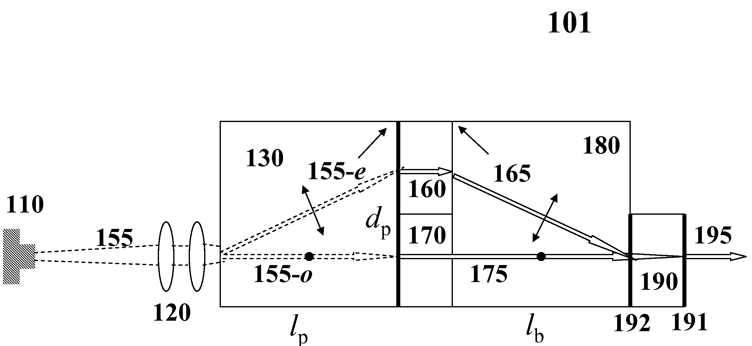
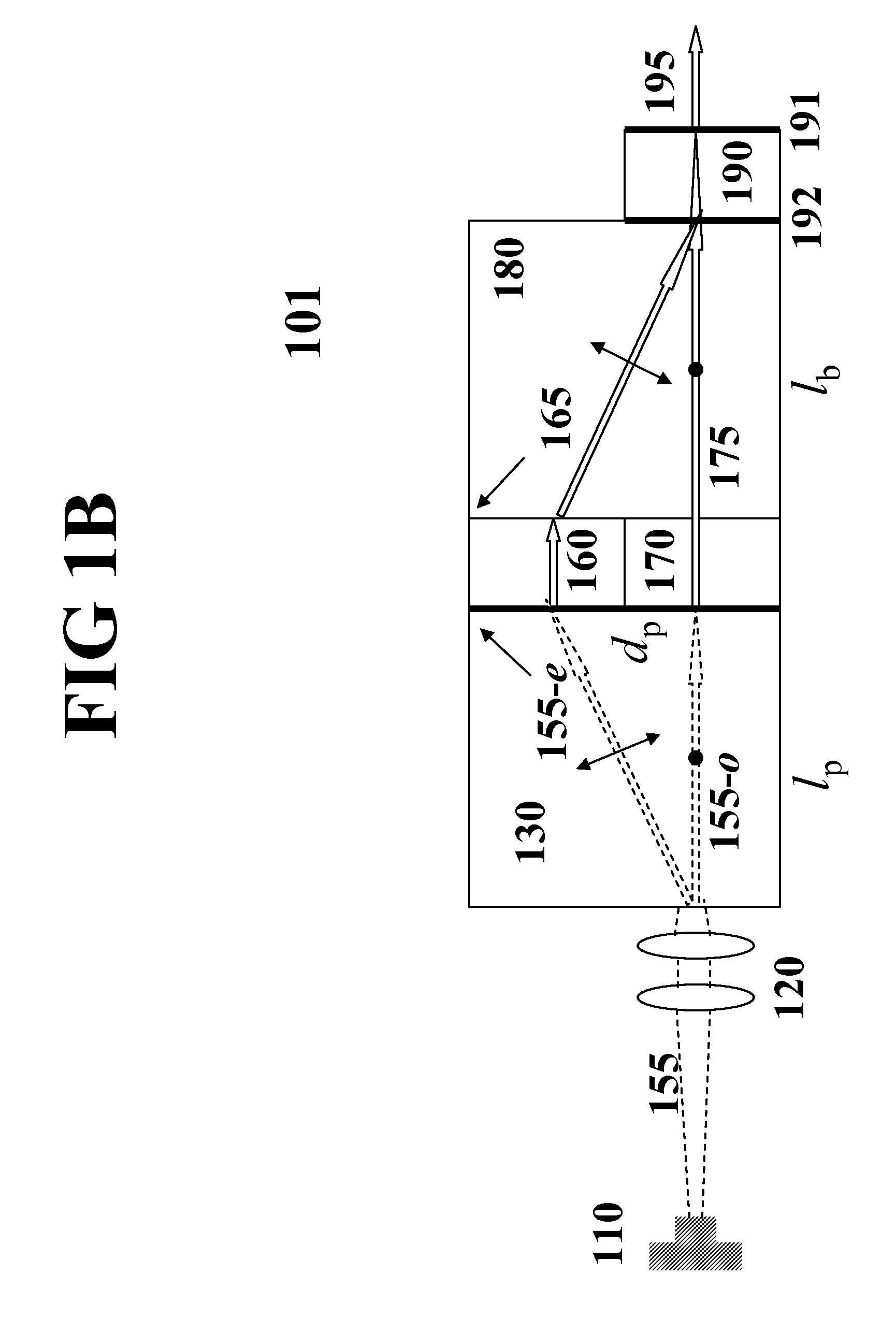
[0025]From the fourth aspect of this invention, one of the fundamental wavelengths can be produced by a laser diode controlled by an RF modulated drive current, while the second fundamental wavelength is produced from a solid-state gain medium. These two fundamental laser beams are combined based on the walk-off effect in a birefringent crystal to generate the desired wavelength by means of SFM in a nonlinear optical crystal. Due to the RF modulation, the laser diode is forced to operate at multimode, leading to low coherence and low speckle noise output.
[0027]From the sixth aspect of this invention, the longitudinal modes of the first and second fundamental beams are inherently spaced unequally. Mode degeneration does not exist during sum frequency mixing. Consequently, the number of longitudinal modes in laser output is multiplied and the mode spacing is narrowed from the input spectra. This greatly reduces speckle noise. In addition, since the output spectrum always consists of unevenly spaced modes, risks associated with self mode locking or Q-switching can be eliminated.

Problems solved by technology

Speckle is a serious problem associated with laser display systems.
However, the success was limited because only a small number of longitudinal modes could be produced.
Unfortunately, there is simply no laser-based RGB light source in existence with these properties.
These approaches, however, may not be suitable for high-speed machine vision systems.
One limitation of such approaches is that the diffusion must occur precisely at the image plane.
In addition, complicated projection lenses are required to provide an intermediate image plane.
However, it is hard to control the illumination brightness while achieving sufficient uniformity in a compact system.
These methods, however, may be insufficient for highly coherent lasers because there are only two uncorrelated components.
Again, the speckle reduction based on these schemes was insignificant.
However, the effects are limited.
One drawback of such image display systems is that they rely upon relatively large and massive moving components, which makes it difficult to achieve real-time projection of high-resolution motion images.
Unfortunately, speckle reduction in the blue spectral range was ineffective.
In addition, the laser operation was limited to pulsed mode, which generally increases amplitude noise, and the speckle reduction was limited.
Previous methods for speckle reduction such as oscillatory motion, active diffuser, diffractive optical elements with or without rotation, wavefront modulation, spatial light modulation based on electromechanical grating, arrays of independent laser emitters, multiple Raman cells, or Doppler shift are complex and cause significant power losses.
In addition, these methods may be ineffective or merely partially effective to some wavelengths that cannot be directly generated from a laser diode or from harmonic generation of a diode-pumped solid-state (DPSS) laser or from an ultra-compact laser based on the SFM schemes.

Method used


Image

  • Low speckle noise monolithic microchip RGB lasers
  • Low speckle noise monolithic microchip RGB lasers
  • Low speckle noise monolithic microchip RGB lasers

Examples


Embodiment Construction

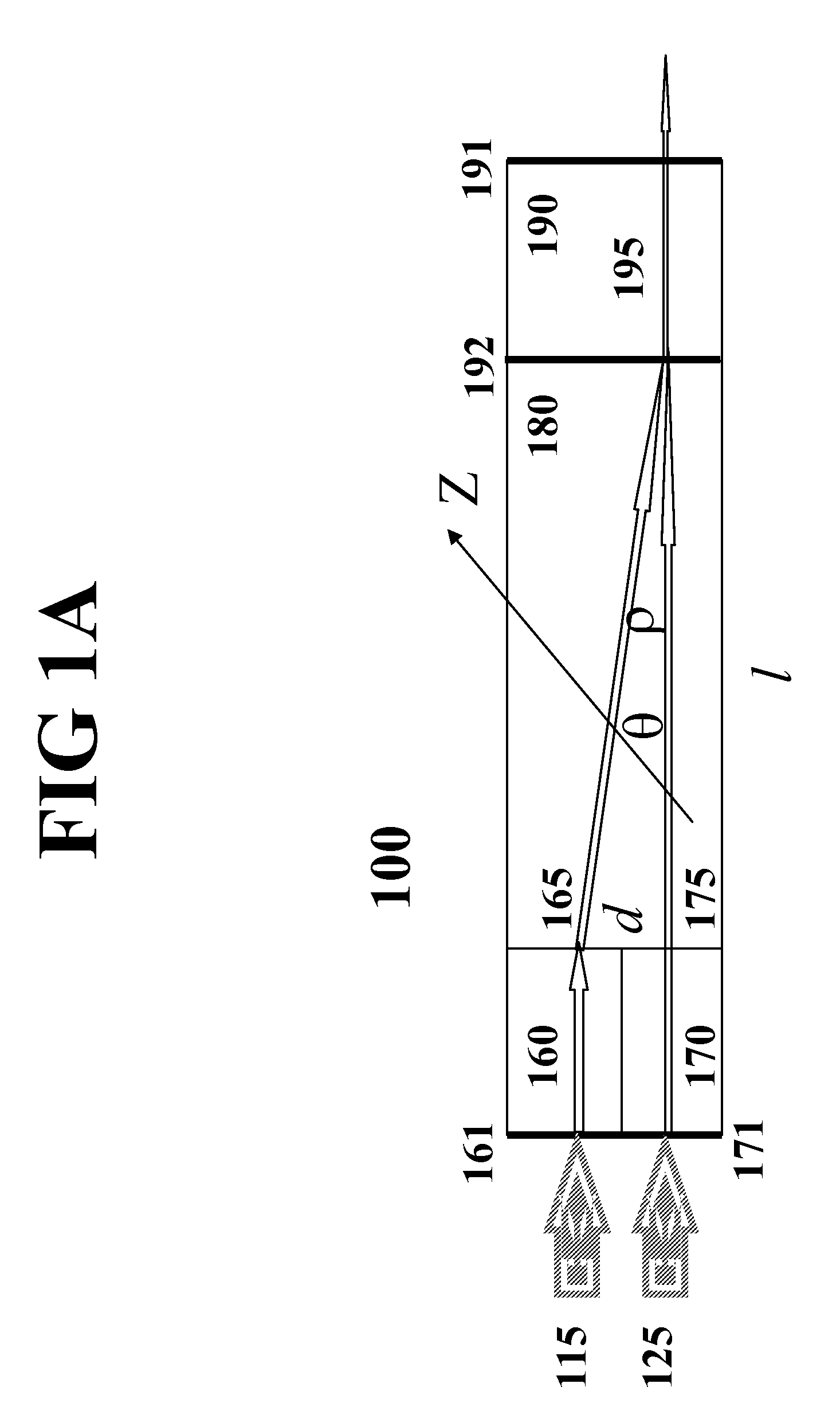
[0040]Referring now to the drawings and in particular to FIG 1A, wherein a first preferred embodiment of the monolithic microchip laser constructed according to the present invention is shown in a schematic form. The monolithic microchip laser 100 comprises pumping lights 115 and 125, laser gain media 160 and 170, a birefringent crystal 180, and a nonlinear optical crystal 190 for sum frequency mixing. These crystals are optically bonded each other. With this monolithic architecture, the intrinsic passive cavity loss is minimized, while the thermal and mechanical stabilities of the cavity are improved.

[0041]For high-efficiency and low-noise operation, the birefringent crystal 180 should be transparent to the fundamental wavelengths, normally in the IR region. Preferably, the birefringent crystal 180 is short in length and has a high birefringence, i.e., wide differences between the refractive indexes of ordinary (o-) and extraordinary (e-) rays. One example of the crystals with thes...


PUM


Abstract

A method for reducing speckle noise of a monolithic microchip laser with intracavity beam combining and sum frequency mixing is based on time averaging of uncorrelated speckle patterns generated from a large number of independent longitudinal modes and comprises schemes including selection of gain media and nonlinear optical materials to support broadband sum frequency mixing; adoption of gain-conjugated and / or chirped mirrors for flat-top spectra and / or mode phase diversification; multimode laser operation introduced by RF modulation; and multiplication of source modes in frequency mixing process featured with degeneration free and narrowed / uneven intervals. A device and an apparatus for generating low speckle noise red, green, blue lasers adaptable for color display systems are developed based on the inventive method.

Description

FIELD OF THE INVENTION[0001]This invention relates generally to solid-state lasers, and in particular to monolithic microchip lasers using intracavity beam combining and sum frequency mixing (SFM) to generate low speckle noise red (R), green (G), blue (B) lights adaptable for image display systems.[0002]In U.S. patent application Ser. No. 11 / 378552, entitled as “Monolithic Microchip Laser with Intracavity Beam Combining and Sum Frequency or Difference Frequency Mixing”, Luo, Zhu, and Lu have disclosed a low-noise monolithic microchip laser, wherein intracavity beam combining and sum frequency mixing or difference frequency mixing (DFM) are used for generation of various lasing wavelengths. According to their invention, two fundamental laser beams are generated from two independent laser oscillator cavities. These two fundamental laser beams are then combined based on the walk-off effect in a birefringent crystal and generate the desired wavelength by means of intracavity SFM or DFM ...

Claims


Application Information

Patent Timeline
IPC IPC(8): H01S3/108
CPCH01S3/0627H01S3/1083H01S3/0606H01S3/0621H01S3/08054H01S3/0809H01S3/09415H01S3/1673H01S3/2383H01S3/2391H01S2301/20H01S3/109
Inventor LUO, NINGYIZHU, SHENG-BAI
Owner PAVILION INTEGRATION
Learn More