Transmissive diffuser with a layer of polytetrafluoroethylene on the output surface for use with an on-orbit radiometric calibration

a polytetrafluoroethylene and diffuser technology, applied in the field of radiometry, can solve the problems of difficult characterization of reflective diffusers, affecting the measurement accuracy of remote sensors, and changing the spectral reflectance characteristics of diffusive reflectors or diffuser panels,

Active Publication Date: 2009-01-27
HARRIS CORP
View PDF11 Cites 10 Cited by
  • Summary
  • Abstract
  • Description
  • Claims
  • Application Information

AI Technical Summary

Problems solved by technology

The spectral reflectance characteristics of the diffusive reflector, or diffuser panel, however, may change with time due to degradation of the diffuser panel.
Since the diffuser panel is employed as the reference source, any change, i.e., degradation of the diffusive surface material, results in a distortion in the measurements of the remote sensor.
One such disadvantage is that reflective diffusers must have a view of the sun at a limited angle, so that the reflected light from the diffuser is seen by the remote sensor.
At very high incidence, or exit angle, a reflective diffuser becomes difficult to characterize.
Materials, such as BaSO4, are brittle or fragile, which increases the probability of failure due to rocket launch vibrations.
In addition, this glass is limited to output angles over which the sunlight scatter may occur.
Ground or frosted glass also has a tendency to be heavy and fragile, resulting in drawbacks for on-orbit use due to rocket launch vibration risks.
Similarly, opal glass or small particulate scatterers in a transparent matrix have a limited spectral range, due to particulate or inclusion size distribution.
Since opal is glass, it also tends to be heavy and fragile, resulting in a drawback for on-orbit use, due to launch vibration risk.
Screens or pinhole arrays also have disadvantages, because their regular geometries may cause undesired diffraction effects.
Screens are also difficult to calibrate over ranges of angles, due to the three-dimensional nature of the screens, which may cause internal shadowing.
Furthermore, pinholes are subject to clogging from extraneous minute particles.
Finally, diffractive scattering material, such as micro-lens arrays or holographic diffusers, have deficiencies in that they have a limited spectral range and a limited range of output angles over which the scatter may occur.
Since they are made from glass, they tend to be heavy and fragile, resulting in drawbacks for on-orbit use, due to launch vibration risks.

Method used


Image

  • Transmissive diffuser with a layer of polytetrafluoroethylene on the output surface for use with an on-orbit radiometric calibration
  • Transmissive diffuser with a layer of polytetrafluoroethylene on the output surface for use with an on-orbit radiometric calibration
  • Transmissive diffuser with a layer of polytetrafluoroethylene on the output surface for use with an on-orbit radiometric calibration

Examples


Embodiment Construction

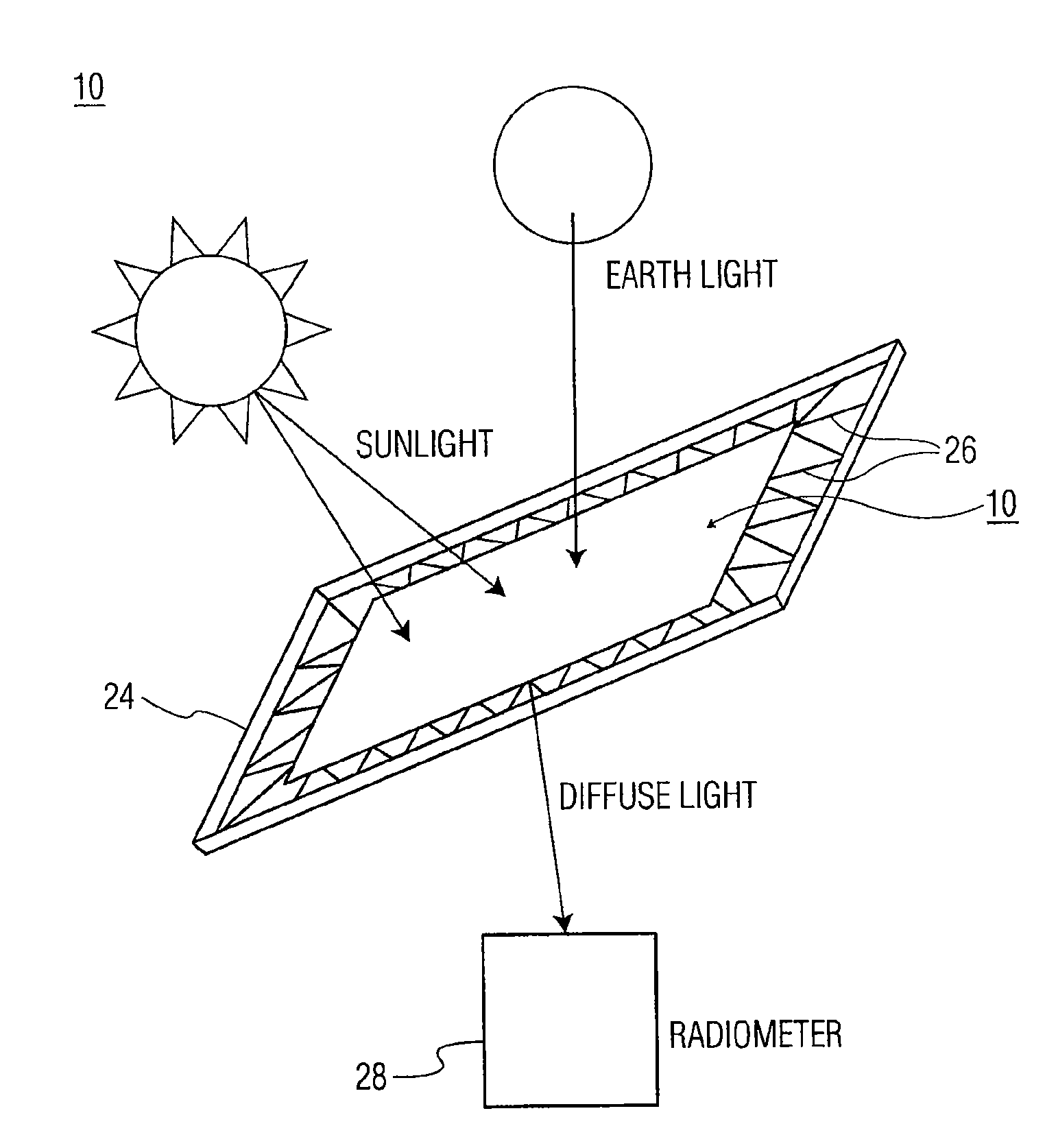
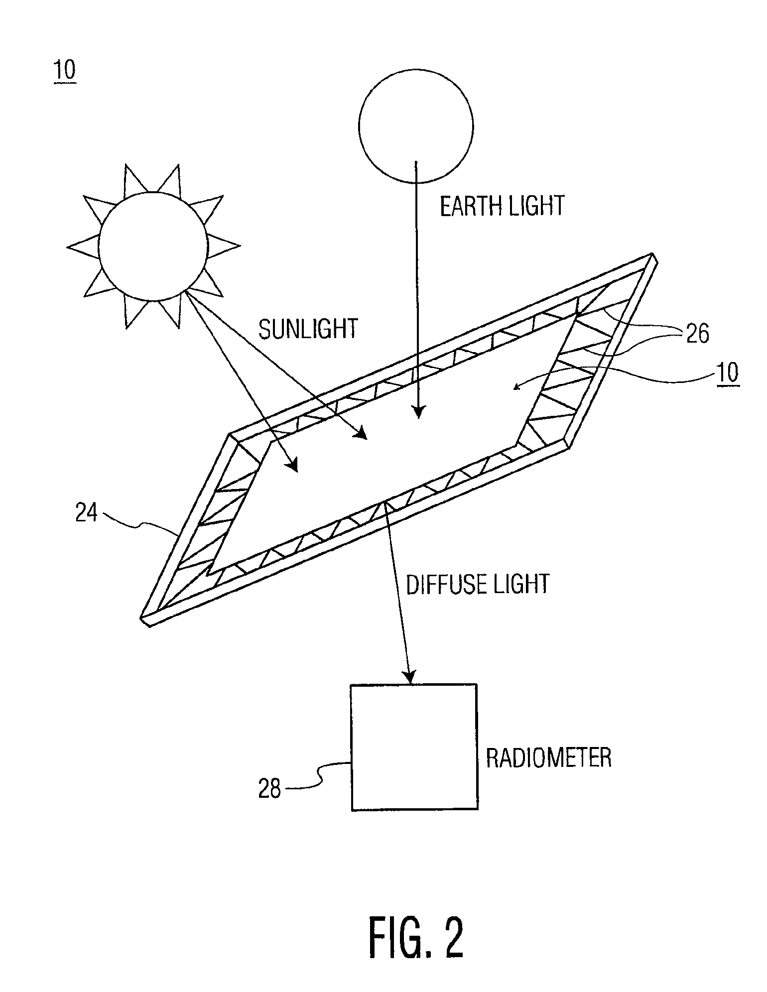
[0030]The present invention provides a unique transmissive diffuser for on-orbit radiometric calibration. In general, a transmissive diffuser may use solar angles that are unavailable to a reflective diffuser. A transmissive diffuser, furthermore, may be made from lightweight, low outgassing, none brittle, radiation stable material that lowers risk of device failure prior to satellite launch and after satellite launch. Moreover, the materials used for the transmissive diffuser includes material already approved for the space environment.

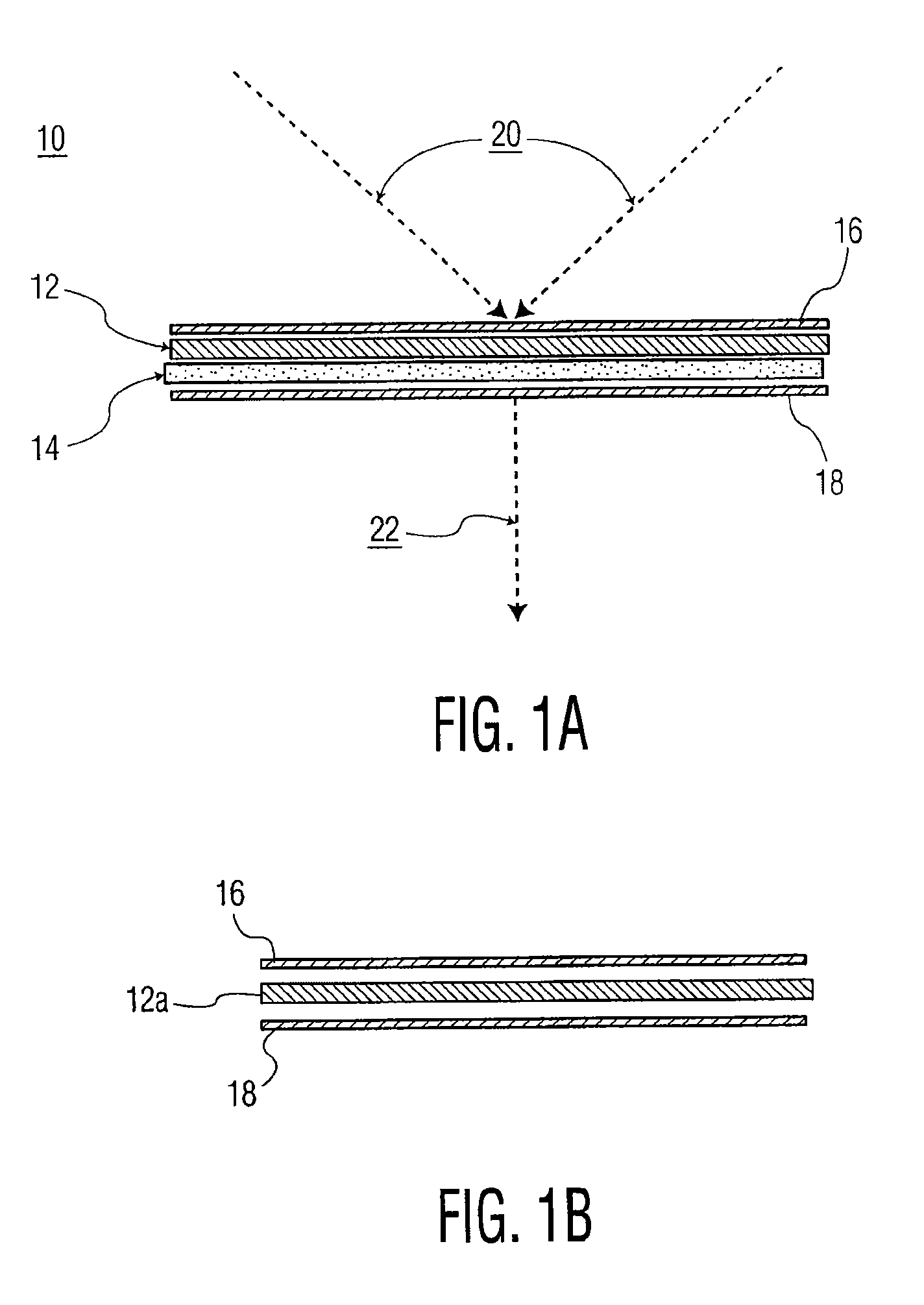
[0031]Referring first to FIG. 1A, there is shown a transmissive diffuser, generally designated as 10. As shown, the transmissive diffuser of the present invention includes a thin fiberglass cloth, generally designated as 12. In the exemplary embodiment shown in FIG. 1A, fiberglass cloth 12 is sandwiched between a first layer of mylar, generally designated as 16, and a thin layer of PTFE / Spectralon™ material, generally designated as 14. Also shown is ...


PUM


Abstract

A flux diffuser for radiometrically calibrating an imaging sensor using the sun as a calibration light source, the flux diffuser including a fiberglass cloth having input and output surfaces. The input surface receives solar irradiance, and the output surface provides diffused scattered light to a radiometer. A layer of mylar may be disposed on top of the input surface. A layer of PTFE or Spectralon™ may be disposed on top of the output surface, and another layer of mylar may be disposed on top of the layer of PTFE or Spectralon™.

Description

TECHNICAL FIELD[0001]The present invention relates, in general, to the field of radiometry and, more specifically, to a system and method for radiometric calibration of remote sensors in space employing solar radiation as a source of radiation.BACKGROUND OF THE INVENTION[0002]Planetary imagers are useful for remote sensing of atmospheric compositions, crop assessments, weather prediction and other types of monitoring activities. Monochromatic and multispectral satellite-based, remote sensors are able to measure properties of the atmosphere above the earth, when their detector arrays are properly calibrated for radiometric response.[0003]A method of calibrating the radiance measured by these remote sensors is to create a reference radiation using a known source of spectral irradiance, such as the sun. The radiation from the sun may be used as a reference signal to a diffusive reflector which, in turn, may provide a known radiance to a remote sensor for calibrating its detector arrays...

Claims


Application Information

Patent Timeline
Patent Type & Authority Patents(United States)
IPC IPC(8): H01J3/14H01J40/14H01J5/16
CPCG01J1/04G01J1/0474G01J1/08G01J5/007G01J5/04G01J5/046G01J5/08G01J5/0878G01J5/522G01J2001/4266G01J5/53
Inventor GALVIN, ROY P.
Owner HARRIS CORP
Why Eureka
Try Eureka