
Cleaning blade for use in image-forming apparatus

a technology of cleaning blade and image forming apparatus, which is applied in the direction of electrographic process, optics, instruments, etc., can solve the problems of excessive wear of the cleaning blade edge, noise-making phenomenon, and difficulty in removing small-diameter spherical polymerized toner that has remained on the surface of the photoreceptor, so as to achieve effective restraint of the cleaning blade and improve the cleaning performance. , the effect of large line pressur

Inactive Publication Date: 2009-02-24
SUMITOMO RUBBER IND LTD
View PDF11 Cites 0 Cited by
  • Summary
  • Abstract
  • Description
  • Claims
  • Application Information

AI Technical Summary

Benefits of technology

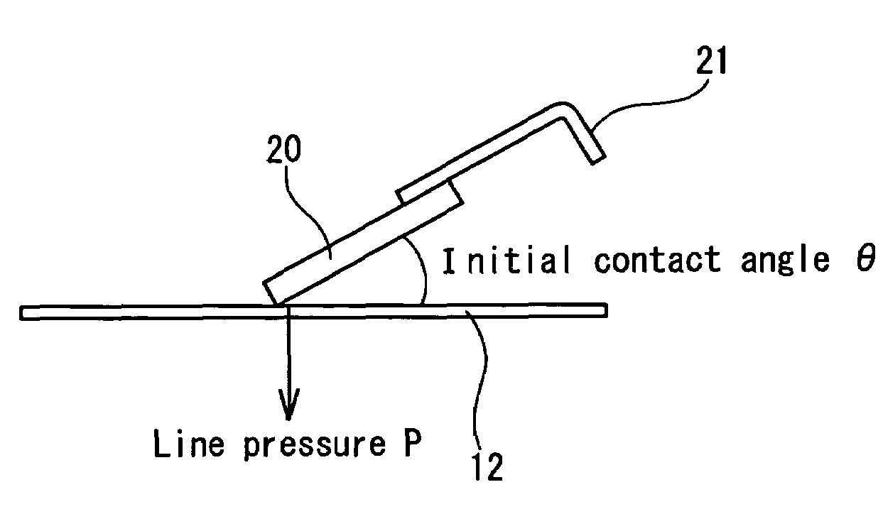
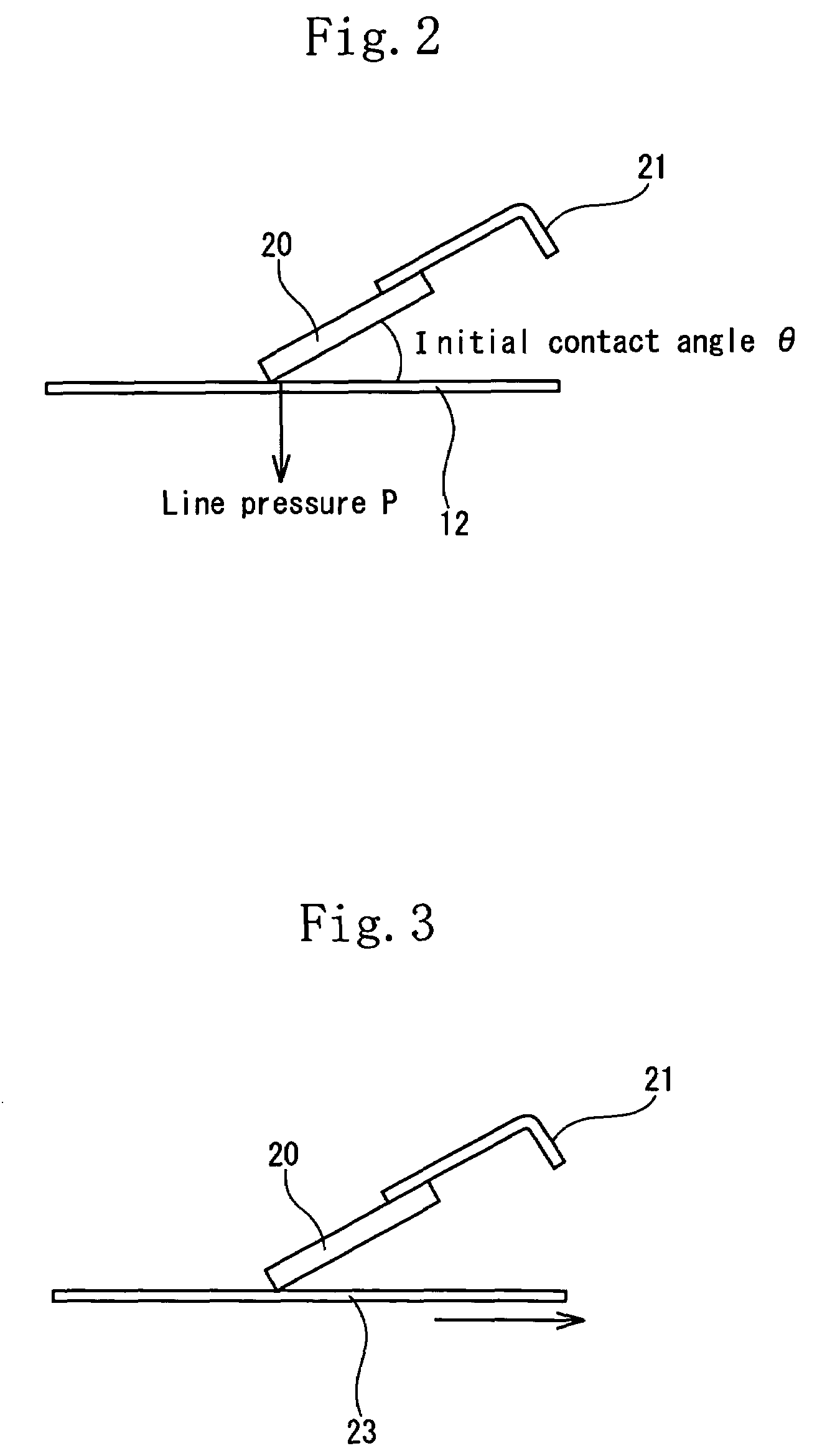
The present invention provides a cleaning blade for an image-forming apparatus that has improved performance in cleaning spherical polymerized toner and is restrained from making noise and presenting a reversal phenomenon at a cleaning time. The cleaning blade is made of a thermosetting elastomer composition containing a rubber component, which is molded into a thin plate. The cleaning blade has an initial contact angle of 10° to 50° and a line pressure of 0.1 N / cm to 1.5 N / cm. The technical effects of the invention are that the cleaning blade has a greatly improved performance in cleaning small-diameter toner, it is restrained from making noise and presenting a reversal phenomenon, and it is able to decrease the coefficient of friction and improve its performance in cleaning the spherical polymerized toner.

Problems solved by technology

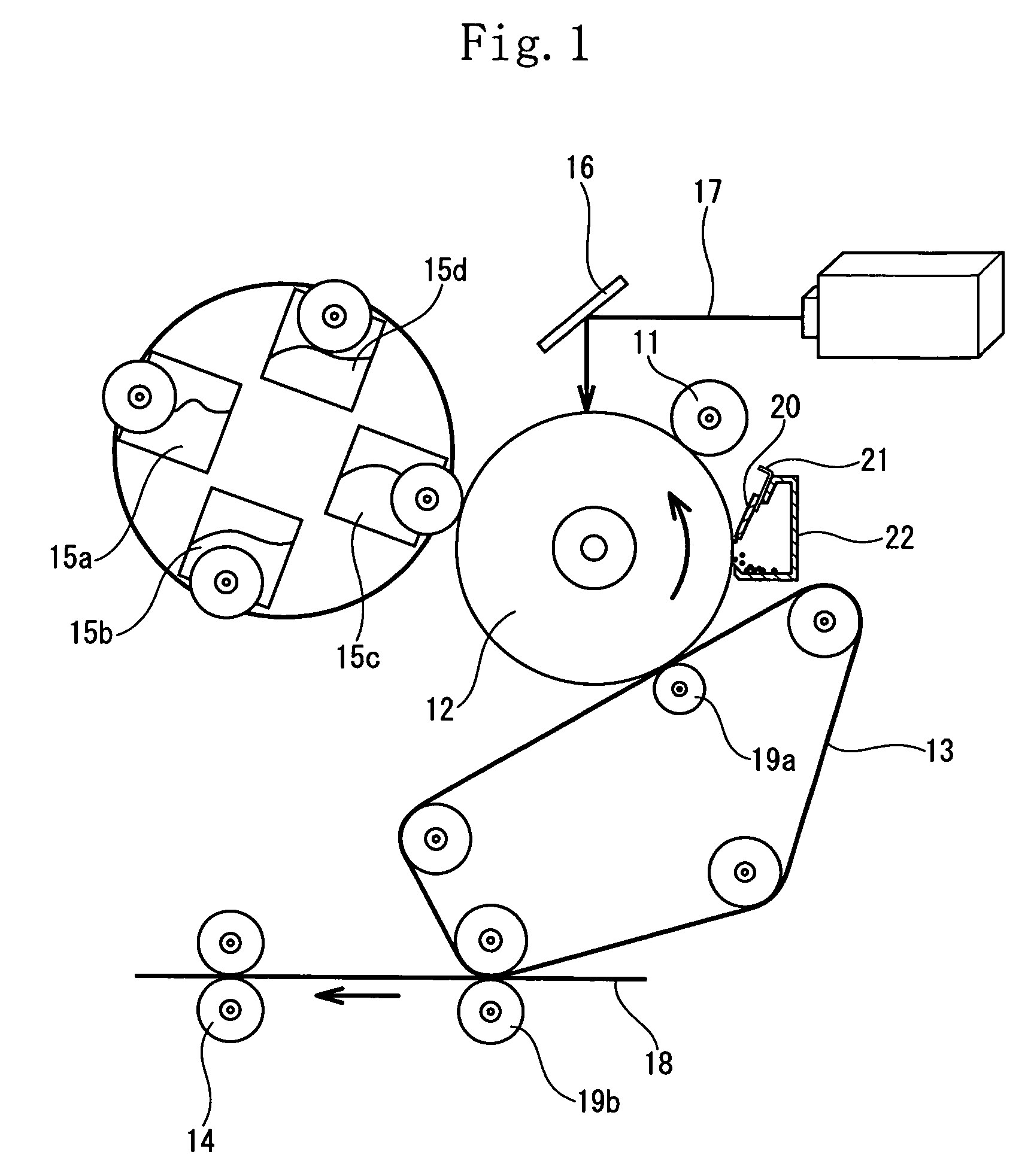
Unless the line pressure of the cleaning blade is increased, it is difficult to remove small-diameter spherical polymerized toner that has remained on the surface of the photoreceptor.
Thereby the edge of the cleaning blade wears excessively, a noise-making phenomenon occurs owing to vibrations caused by sliding contact between the cleaning blade and the photoreceptor, and a reversal phenomenon that the edge of the cleaning blade is moved in the rotational direction of the photoreceptor occurs.
Thus it is difficult to increase the line pressure in the case of the cleaning blade composed of the polyurethane rubber.
Thus, considering that the cleaning blade is pressed against the photoreceptor in performing a cleaning operation, there is a fear that the surface of the photoreceptor is damaged by the cleaning blade because it has a low degree of elastic deformation and a high hardness not less than 90 degrees in JIS-A hardness.
Consequently the number of processes increases and the cost of manufacturing the cleaning blade increases.
Thus the cleaning blade has problems in productivity.
As a result, the cleaning blade did not have preferable cleaning performance.

Method used


Image

  • Cleaning blade for use in image-forming apparatus
  • Cleaning blade for use in image-forming apparatus
  • Cleaning blade for use in image-forming apparatus

Examples


examples

[0136]Examples of the present invention and comparison examples are described below.

examples 1 through 4

and Comparison Examples 1 Through 4

[0137]After the mixing amount of each of the rubber component (1) and the filler (2) shown in table 1 was measured, the rubber component (1) and the filler (2a, 2b) were supplied to a rubber kneading apparatus such as a twin screw extruder, an open roll or a Banbury mixer. Thereafter they were kneaded for five to six minutes while they were being heated to 80° C. to 120° C.

[0138]The obtained mixture and the crosslinking agent (3) were supplied to the rubber kneading apparatus such as the open roll, the Banbury mixer or the kneader. The mixing amount of the crosslinking agent (3) is shown in table 1. Thereafter they were kneaded for five to six minutes while they were being heated to 80° C. to 90° C.

[0139]After the obtained rubber composition was set in a die, it was press-vulcanized at 160° C. to 170° C. for 20 to 40 minutes to obtain a sheet having a thickness of 2 mm.

[0140]After a cleaning blade having a width of 27 mm and a length of 320 mm was ...


PUM

PropertyMeasurementUnit
contact angleaaaaaaaaaa

Abstract

A cleaning blade, for use in an image-forming apparatus, which is formed by molding a thermosetting elastomer composition containing a rubber component consisting of acrylonitrile-butadiene rubber, natural rubber, butadiene rubber, styrene-butadiene rubber, isoprene rubber, butyl rubber, chloroprene rubber, acrylic rubber, epichlorohydrin rubber, ethylene propylene rubber, and ethylene-propylene-diene copolymer rubber or a mixture of two or more of the rubbers into a thin plate. An initial contact angle of the cleaning blade to the photoreceptor is set to 10° to 50°. A line pressure of the cleaning blade to be applied to the photoreceptor is set to 0.1 N / cm to 1.5 N / cm.

Description

[0001]This nonprovisional application claims priority under 35 U.S.C. § 119(a) on Patent Application No(s). 2005-368723 filed in Japan on Dec. 21, 2005, the entire contents of which are hereby incorporated by reference.FIELD OF THE INVENTION[0002]The present invention relates to a cleaning blade for use in an image-forming apparatus and more particularly to a cleaning blade which has a greatly improved performance in cleaning spherical polymerized toner having a small diameter.[0003]In an electrostatic photocopying machine in which ordinary paper is used as recording paper, a copying operation is performed as follows: an electrostatic charge is applied to the surface of a photoreceptor by discharge, an image is exposed to the photoreceptor to form an electrostatic latent image thereon, toner having an opposite polarity is attached to the electrostatic latent image to develop the electrostatic latent image, a toner image is transferred to recording paper, and the recording paper to w...

Claims


Application Information

Patent Timeline
Patent Type & Authority Patents(United States)
IPC IPC(8): G03G21/00
CPCG03G21/0017G03G2221/0005Y10S525/94G03G21/00
Inventor SUGIMOTO, MUTSUKI
Owner SUMITOMO RUBBER IND LTD
Learn More