Miniaturized optically imaging system with high lateral and axial resolution
a technology of optical imaging and axial resolution, applied in the field of miniaturized optical imaging system with high can solve the problems of limited lateral and axial resolution capacity, clear deficiency, and inability to achieve imaging quality, and achieve the effect of improving photon efficiency and achieving higher lateral and axial spatial resolution
- Summary
- Abstract
- Description
- Claims
- Application Information
AI Technical Summary
Benefits of technology
Problems solved by technology
Method used
Image
Examples
1st embodiment example
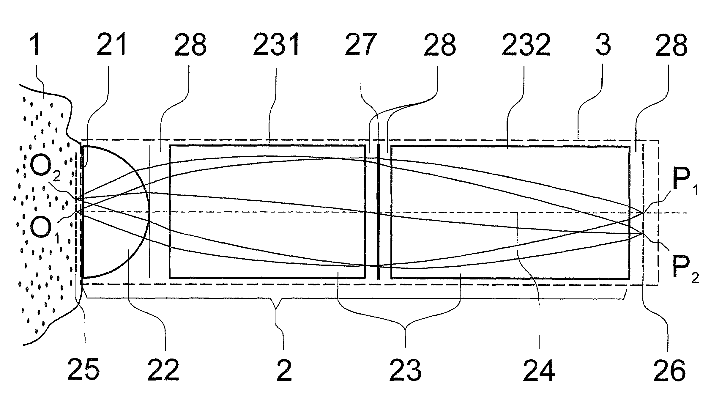
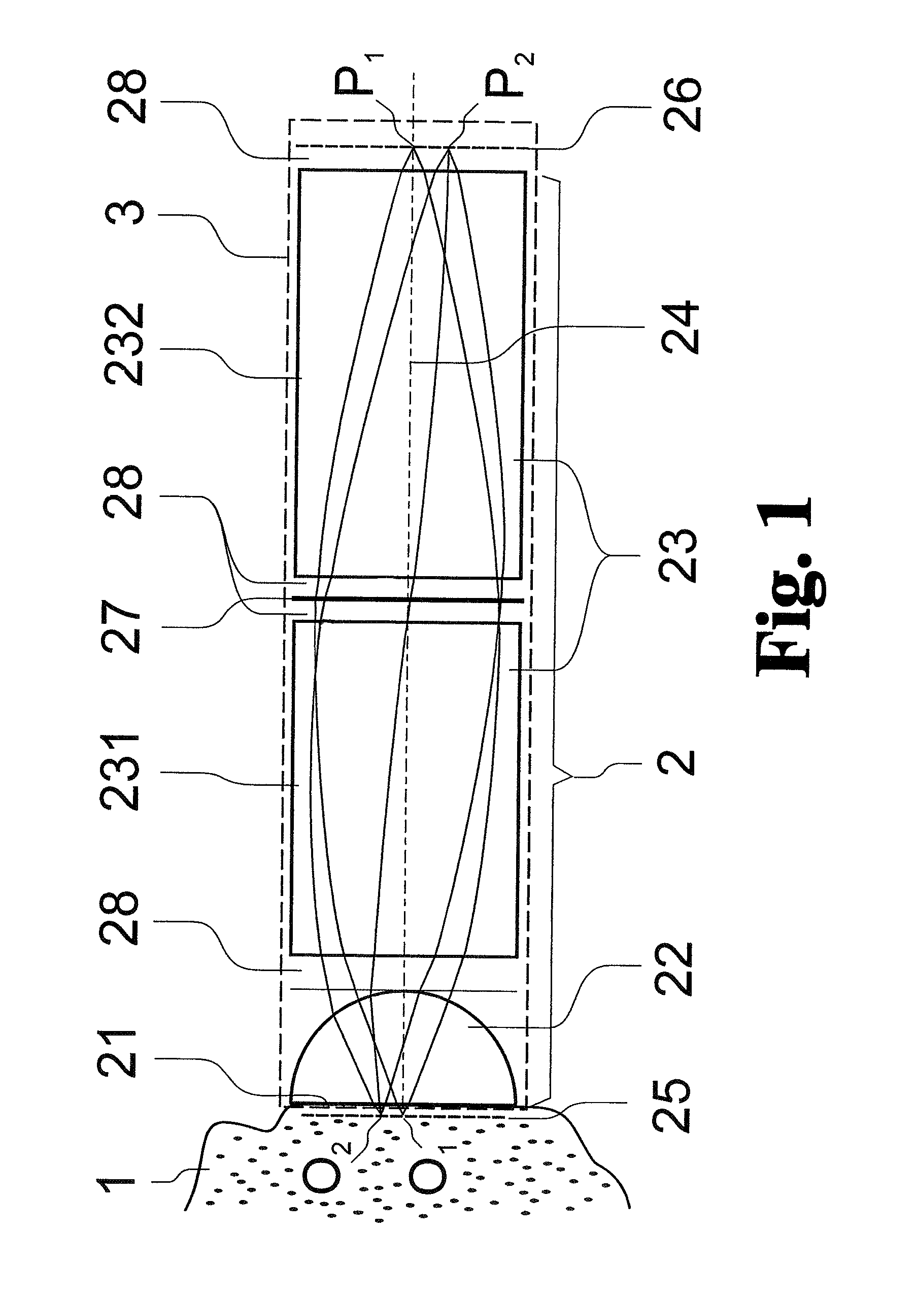
[0059]In a concrete embodiment form according to FIG. 5, the optical system 2 has two identical GRIN lenses 231 and 232 with a nominal numerical aperture of 0.5 and a diameter of 1.0 mm. Achromatization is achieved for 830 nm and 500 nm by the diffractive lens 27 between the two GRIN lenses 231 and 232.
[0060]The object 1 is located at the entrance surface 21 of the object-side GRIN lens 231 having a thickness of 2.403 mm.
[0061]The refractive index profile of the two GRIN lenses 231 and 232 is reduced to a polynomial formulation at a reference wavelength λref=0.67 μm:
nref(r)=n0+nr2r2+nr4r4 (1)
where r is the radial coordinate and n0, nr2, nr4 are the refractive index profile parameters. The dependency of the refractive index profile on wavelength λ is described by the following dispersion model:
n2(λ)=n2(λref)+K1(λ2−λ2ref) / λ2 (2)
where n2(λref)=n2ref and K1 is a function of nref.
K1 is described by the linear equation:
K1(nref)=K11+K12n2ref (3)
[0062]Both GRIN lenses 231 and 232 have th...
2nd embodiment example
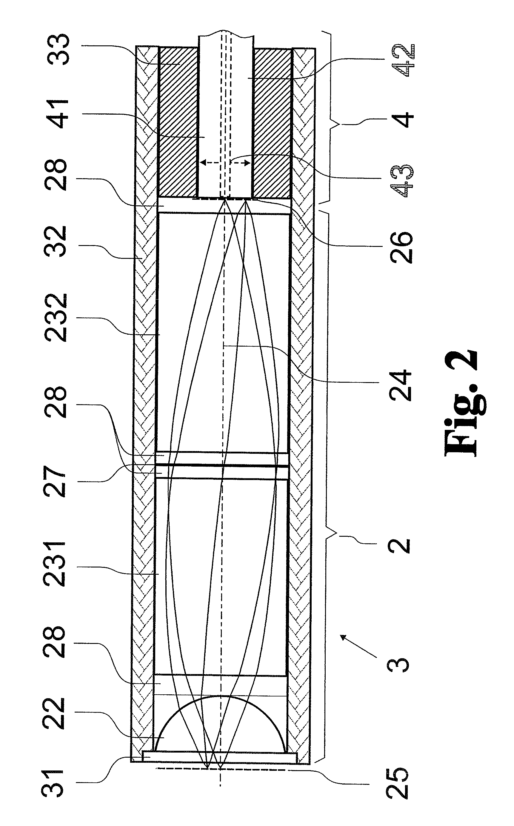
[0070]In another specific construction according to the basic optical scheme of FIG. 4, the miniature optical head 3 comprises an optical window 31 (material: BK7) with a thickness of 0.170 mm, a spherical lens element 22 (material: LaSFN9, spherical radius: 0.5 mm, thickness: 0.30 mm), two GRIN lenses 231 and 232 with a diameter of 1.0 mm, and a nominal numerical aperture of 0.5. Achromatization for 830 nm and 500 nm is achieved through a diffractive lens 27 between the two GRIN lenses 231 and 232.
[0071]All optical elements are in direct contact (as is shown in FIG. 4), i.e., there are no gaps 28 along the optical axis 24. This choice of optical design is advantageous for the alignment of the entire optical system 2 within the mechanical mount 32 with miniaturized head 3, particularly because of the very small diameters of the optical elements (1 mm).
[0072]In this instance, the object 1 is in water at a working distance of 50 μm from the entrance surface 21 of the object-side spher...
third embodiment example
[0079]Miniature optical head comprising two GRIN lenses with 1.0 diameter. The object-side GRIN lens has a nominal numerical aperture of 0.5, the image-side GRIN lens has a nominal numerical aperture of 0.2, and an achromatization is achieved for 830 nm and 500 nm by a diffractive lens between the two GRIN lenses. The object is located in the entrance surface of the object-side GRIN lens having a thickness of 2.403 mm.
[0080]As in the first embodiment example above, the refractive index profile of the two GRIN lenses 231 and 232 is defined by the equations (1), (2) and (3) and is calculated for a reference wavelength of λref=0.67 μm. Because of the different numerical apertures, they are characterized by different refractive index profiles, and the dependency of the profiles on wavelength also diverges.
[0081]For the object-side lens (NA=0.5), the refractive index profile is described by the following parameters:[0082]K11=0.11098;[0083]K12=−0.06172;[0084]n0=1.6289;[0085]nr2=−0.3482;[0...
PUM
 Abstract
Description
Claims
Application Information
 - R&D
- Intellectual Property
- Life Sciences
- Materials
- Tech Scout
- Unparalleled Data Quality
- Higher Quality Content
- 60% Fewer Hallucinations
Browse by: Latest US Patents, China's latest patents, Technical Efficacy Thesaurus, Application Domain, Technology Topic, Popular Technical Reports.
© 2025 PatSnap. All rights reserved.Legal|Privacy policy|Modern Slavery Act Transparency Statement|Sitemap|About US| Contact US: help@patsnap.com


