
Method and apparatus for producing resin particles using granulation-prevention agent, and resin particles produced by the method

a technology of granulation prevention agent and resin particle, which is applied in the field of method of producing resin particle and resin particle produced by method, can solve the problems of difficult to sufficiently enhance the strength of resin particle, low strength of resin particle produced in such a manner, and high cost of production, so as to achieve the effect of increasing the amount of toner to be packed in the cartridge, superior electrification properties and durability, and increasing the bulk density of toner

Inactive Publication Date: 2009-04-07
SEIKO EPSON CORP
View PDF3 Cites 13 Cited by
  • Summary
  • Abstract
  • Description
  • Claims
  • Application Information

AI Technical Summary

Benefits of technology

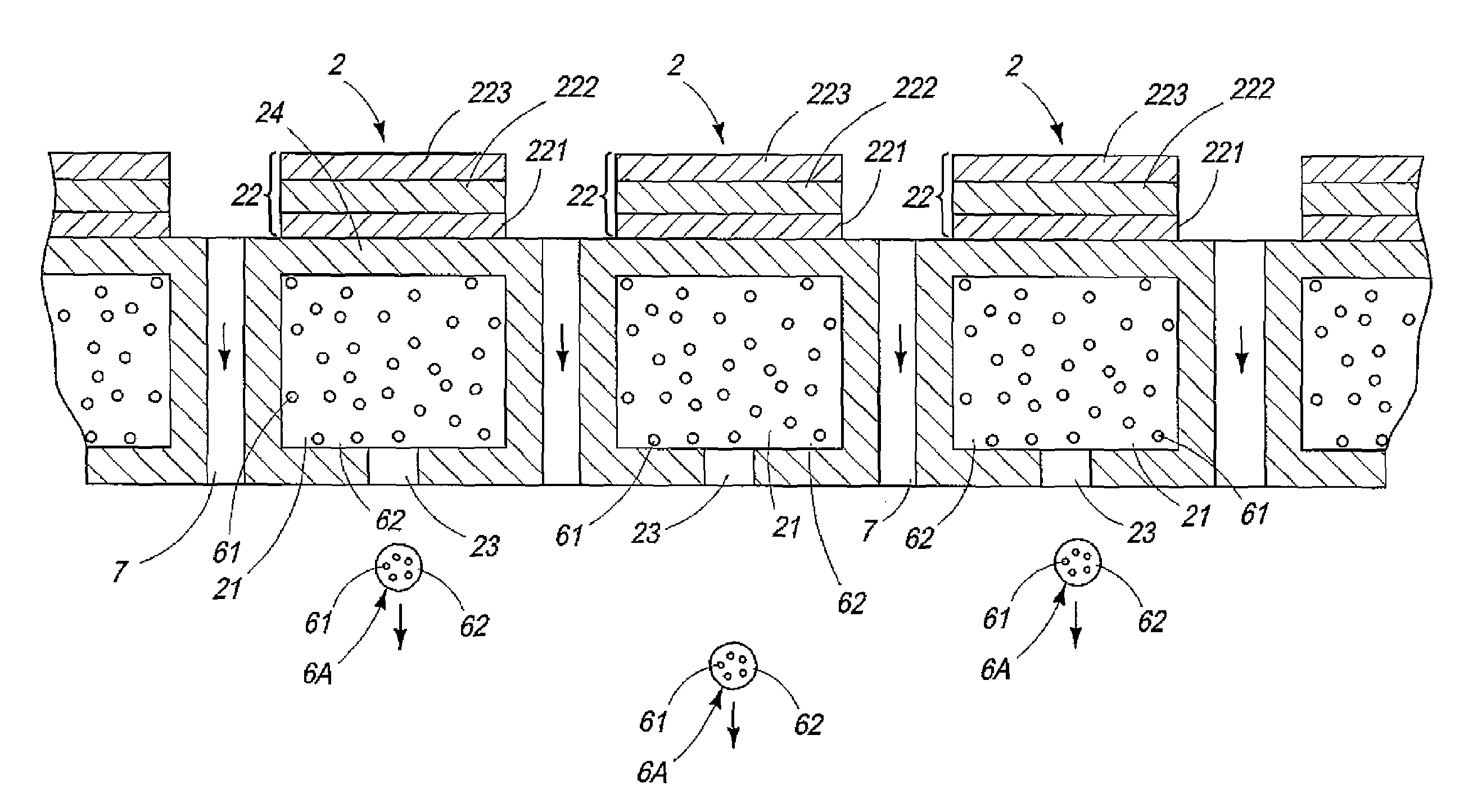
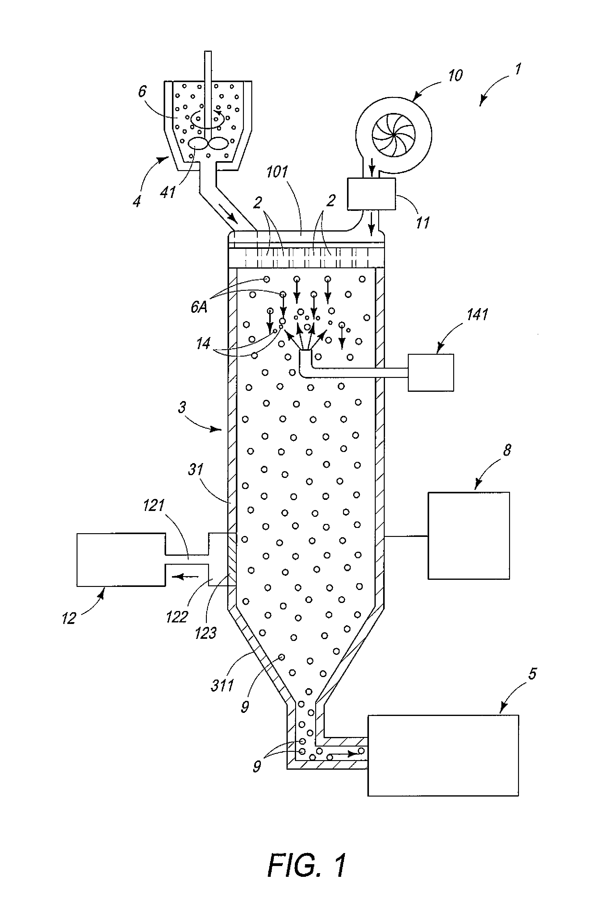
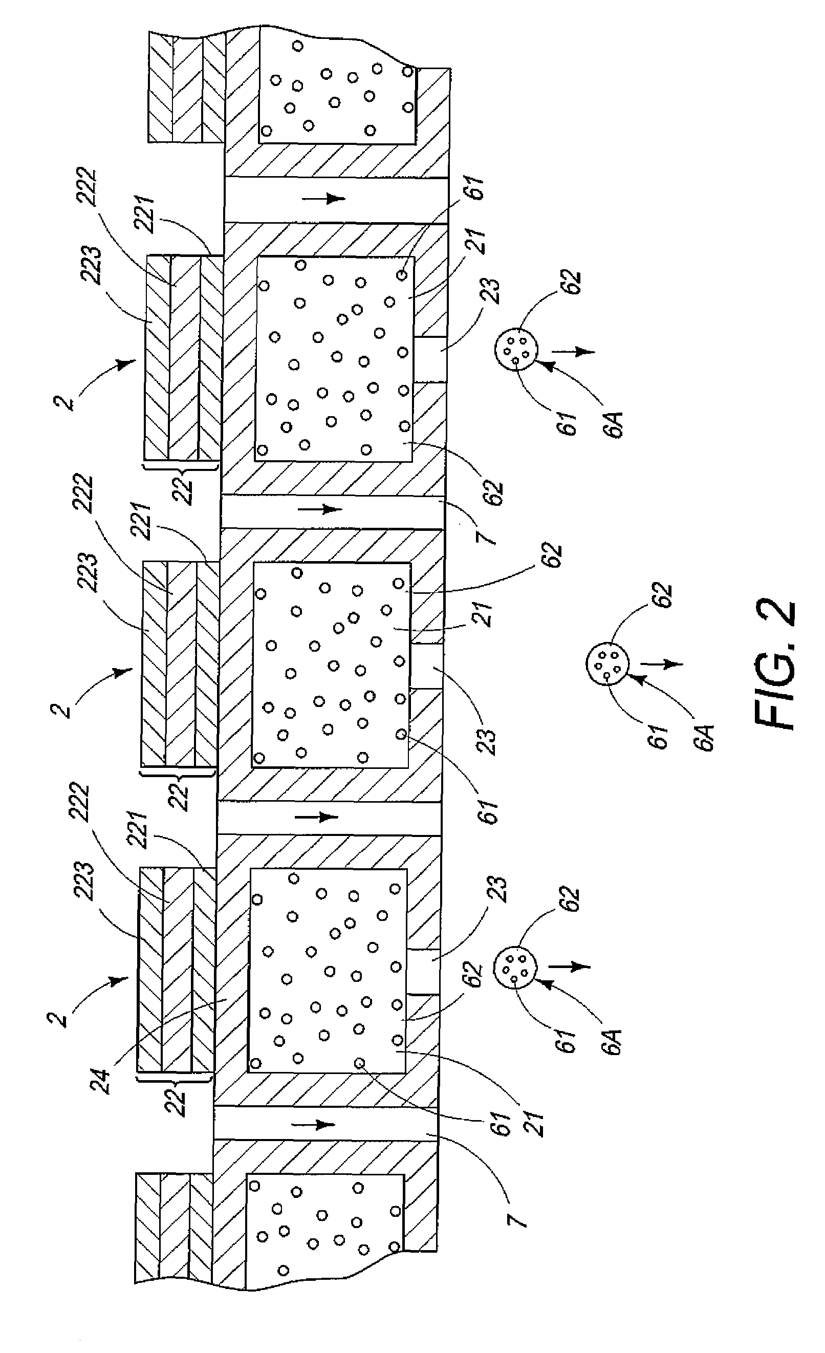
The present invention provides a method for producing resin particles with superior mechanical strength and uniform shape. The method involves ejecting a dispersion liquid in which a dispersoid is finely dispersed in a dispersion medium and removing the dispersion medium from the dispersion liquid. A granulation prevention agent is applied to the dispersion liquid to prevent the fine particles from agglomerating and then granulating. The resulting resin particles have uniform particle size distribution and are not degenerated. The use of inorganic fine particles as a constituent material of the granulation prevention agent prevents the formation of voids or defects in the particles. The method also prevents the fine particles from agglomerating with each other and enables the formation of individual fine particles in the dispersion medium. The average particle diameter of the granulation prevention agent should be in the range of 0.02 to 1.0 μm to effectively prevent agglomeration. The dispersion liquid should be heated at a temperature equal to or lower than the glass transition point of the resin material constituting the dispersoid to remove the dispersion medium while preventing agglomeration of the fine particles.

Problems solved by technology

However, in this method, since each of the resin particles is an agglomerate composed of such fine particles derived from the dispersoid as described above, the resin particles are likely to be broken up between the fine particles, namely the resin particles produced in such a manner have low strength.
However, even in the case where such an approach is used, it is still difficult to sufficiently enhance the strength of the resin particles.
In addition, the resin particles obtained in this manner may not have desired properties due to undesirable degeneration of the resin constituting the resin particles.
Further, in this method, if the droplets of the dispersion liquid are heated at a relatively high temperature in order to remove the dispersion medium quickly from the droplets to obtain the agglomerates, there is a case that fine particles derived from the dispersoid are bonded unnecessarily with each other before being agglomerated.
In such a case, it becomes difficult to remove the dispersion medium from the inside of the droplets, which results in a case that the obtained agglomerates have voids and different shapes.
In a case where such resin particles are used as a toner, there is a possibility of causing defective charge since toner particles cannot be frictionally charged with each other when forming a toner image.
Further, there is also a possibility of causing improper transfer of a toner when electrostatically attaching toner particles to a photoconductive drum.

Method used


Image

  • Method and apparatus for producing resin particles using granulation-prevention agent, and resin particles produced by the method
  • Method and apparatus for producing resin particles using granulation-prevention agent, and resin particles produced by the method
  • Method and apparatus for producing resin particles using granulation-prevention agent, and resin particles produced by the method

Examples


example 1

[0217]First, 100 parts by weight of an epoxy resin (a modified epoxy resin, glass transition point Tg: 70° C., melting point Tm: 110° C. manufactured by Arakawa Chemical Industries, LTD.) as a binder resin. 5 parts by weight of a phthalocyanine pigment (phthalocyanine blue, manufactured by Dainichiseika Color & Chemicals Mfg. Co., Ltd.) as a coloring agent, and 300 parts by weight of tetrahydrofuran (manufactured by Wako Pure Chemical Industries, Ltd) as a solvent were prepared.

[0218]These components were mixed and dispersed using a ball mill for 10 hours to prepare a resin solution (a resin liquid).

[0219]At the same time, 10 parts by weight of sodium polyacrylate (average degree of polymerization n=2,700 to 7,500, manufactured by Wako Pure Chemical Industries, Ltd.) as a dispersant was dissolved in 590 parts by weight of ion-exchange water to prepare an aqueous solution.

[0220]Next, 600 parts by weight of the aqueous solution was poured into a 3-liter round-bottom stainless containe...

example 2

[0231]A toner was produced in the same manner as in Example 1 except that the resin was changed to a styrene-acrylic ester copolymer (glass transition point Tg: 52° C., melting point Tm: 105° C.).

example 3

[0232]A toner was produced in the same manner as in Example 1 except that the granulation prevention agent was changed to titanium oxide having an average particle diameter of 30 nm which had been subjected to hydrophilic treatment, and it was injected so that the amount of the granulation prevention agent contained in the finally obtained toner powder was 1.0 wt %.


PUM

PropertyMeasurementUnit
particle diameteraaaaaaaaaa
densityaaaaaaaaaa
boiling pointaaaaaaaaaa

Abstract

A method for producing resin particles using a dispersion liquid in which a dispersoid mainly made of a resin material is finely dispersed in a dispersion medium, the method comprising a dispersion liquid ejecting step for ejecting the dispersion liquid in the form of droplets and a dispersion medium removing step for removing the dispersion medium from the dispersion liquid in the form of droplets, wherein a granulation prevention agent for preventing or suppressing fine particles derived from the dispersoid from being agglomerated and then granulated is applied to the dispersion liquid.

Description

CROSS-REFERENCE[0001]The entire disclosure of Japanese Patent Application No. 2004-342040 filed on Nov. 26, 2004 is expressly incorporated by reference herein.BACKGROUND OF THE INVENTION[0002]1. Field of the Invention[0003]The present invention relates to a method for producing resin particles and resin particles produced by the method.[0004]2. Description of the Prior Art[0005]Toners for use in image formation apparatuses employing an electrophotographic system such as printers, copiers, facsimile machines and the like, and powdered paints are formed using fine particles mainly made of a resin material (hereinafter, referred to as “resin particles”).[0006]As for one example of a method for producing such resin particles, a method disclosed in JP-A No. 2004-070303 is known. In this method, droplets of a dispersion liquid in which a dispersoid containing a resin material is finely dispersed in a dispersion medium are solidified to thereby obtain resin particles.[0007]In this method, ...

Claims


Application Information

Patent Timeline
Patent Type & Authority Patents(United States)
IPC IPC(8): B32B5/16B28B1/54
CPCC08J3/122C08J3/16C09D5/031C09D5/033C09D7/1216C09D7/1266C09D7/1275C09D7/1283G03G9/0804G03G9/0819G03G9/0821G03G9/0827C08J3/124Y10T428/2982C08K3/22C08K3/36Y10T428/2991C09D7/61C09D7/67C09D7/68C09D7/69
Inventor AKIOKA, KOJIYAMAGAMI, TOSHIAKIKAIHO, HIROSHIIKUMA, KEN
Owner SEIKO EPSON CORP
Learn More