Method of developing subsurface freeze zone

a freeze zone and subsurface technology, applied in the direction of survey, insulation, borehole/well accessories, etc., can solve the problems of limiting the application of very shallow formations, the decomposition of kerogen, and the discontinuation of practice, so as to reduce the natural reduce the salinity of in situ water, and reduce the effect of in situ water freezing temperatur

Inactive Publication Date: 2009-04-14
EXXONMOBIL UPSTREAM RES CO
View PDF108 Cites 37 Cited by
  • Summary
  • Abstract
  • Description
  • Claims
  • Application Information

AI Technical Summary

Benefits of technology

[0019]The methods described herein have various benefits in improving the cooling efficiency of certain prior art methods. In various embodiments, such benefits may include the reduction of cooling losses to the overburden, reducing the amount of fluid needed to be circulated, or speeding the formation of an impermeable freeze zone.
[0020]A method for lowering the temperature of a subsurface formation is provided. Preferably, the subsurface formation comprises oil shale. The method includes the step of injecting a cooling fluid under pressure into a wellbore, with the wellbore having been completed at or below a depth of the subsurface formation. The wellbore has an elongated tubular member for receiving the cooling fluid and for conveying it downhole to the subsurface formation. The wellbore has a first expansion valve in fluid communication with the tubular member through which the cooling fluid flows. The cooling fluid is expanded as it flows through the first expansion valve. In this way, the temperature of the cooling fluid is reduced. The temperature of the surrounding formation is then likewise reduced through thermal conduction and convection, or cold energy.
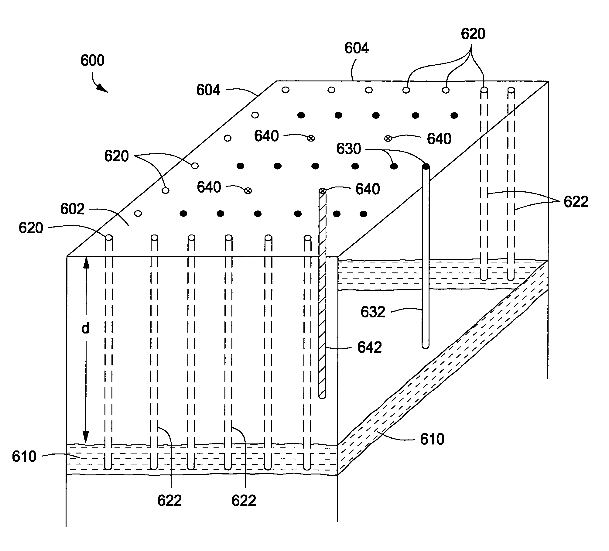
[0036]Preferably, the subsurface formation holds in situ water. Further, the cooling fluid preferably cools the subsurface formation to a sufficient extent to freeze at least a portion of the in situ water. In one aspect, the method further includes the step of injecting low salinity water into at least a portion of the subsurface formation to reduce the natural salinity of the in situ water and to raise the freezing temperature of the in situ water.
[0039]Use of a slurry can have the benefit of significantly increasing the “cold energy” carried by the cooling fluid per mass of fluid. Moreover, a slurry can maintain a relatively constant temperature even as it loses “cold energy” due to the latent heat of fusion of the solids.
[0040]The wellbore is completed at or below a depth of the subsurface formation. The wellbore has a bore formed through the subsurface formation that defines a diameter. In this case no downhole expansion valve is required. Use of a slurry can have the extra benefit of removing or reducing the need for insulation between the upward and downward flows since the slurry can be maintained at a relatively constant temperature as long as frozen solids are still present.
[0042]Preferably, the subsurface formation holds in situ water. Further, the cooling fluid cools the subsurface formation to a sufficient extent to freeze at least a portion of the in situ water. In one aspect, the method further includes the step of injecting low salinity water into at least a portion of the subsurface formation to reduce the natural salinity of the in situ water and to raise the freezing temperature of the in situ water.

Problems solved by technology

Kerogen is subject to decomposing upon exposure to heat over a period of time.
However, the practice has been mostly discontinued in recent years because it proved to be uneconomical or because of environmental constraints on spent shale disposal.
Further, surface retorting requires mining of the oil shale, which limits application to very shallow formations.
While research projects have been conducted in this area from time to time, no serious commercial development has been undertaken.

Method used


Image

  • Method of developing subsurface freeze zone
  • Method of developing subsurface freeze zone
  • Method of developing subsurface freeze zone

Examples


Embodiment Construction

Definitions

[0059]As used herein, the term “hydrocarbon(s)” refers to organic material with molecular structures containing carbon bonded to hydrogen. Hydrocarbons may also include other elements, such as, but not limited to, halogens, metallic elements, nitrogen, oxygen, and / or sulfur.

[0060]As used herein, the term “hydrocarbon fluids” refers to a hydrocarbon or mixtures of hydrocarbons that are gases or liquids. For example, hydrocarbon fluids may include a hydrocarbon or mixtures of hydrocarbons that are gases or liquids at formation conditions, at processing conditions or at ambient conditions (15° C. and 1 atm pressure). Hydrocarbon fluids may include, for example, oil, natural gas, coalbed methane, shale oil, pyrolysis oil, pyrolysis gas, a pyrolysis product of coal, and other hydrocarbons that are in a gaseous or liquid state.

[0061]As used herein, the terms “produced fluids” and “production fluids” refer to liquids and / or gases removed from a subsurface formation, including, f...


PUM


Abstract

A method for lowering the temperature of a portion of a subsurface formation is provided. Preferably, the formation is an oil shale formation. The method includes the step of injecting a cooling fluid under pressure into a wellbore, with the wellbore having been completed at or below a depth of the subsurface formation. In one embodiment the wellbore has an elongated tubular member for receiving the cooling fluid and for conveying it downhole to the subsurface formation. The wellbore also has an expansion valve in fluid communication with the tubular member through which the cooling fluid flows. The method then includes the steps of injecting a cooling fluid under pressure into the wellbore, and expanding the cooling fluid across the first expansion valve. In this way, the temperature of the cooling fluid is reduced. The temperature of the surrounding formation is likewise reduced through thermal conduction and convection. In another embodiment, a partially frozen slurry is used as the cooling fluid.

Description

CROSS-REFERENCE TO RELATED APPLICATIONS[0001]This application claims the benefit of U.S. Provisional application 60 / 851,543 which was filed on Oct. 13, 2006. The provisional application is incorporated herein in its entirety by reference. This application is also related to co-pending, concurrently filed, and commonly assigned U.S. patent application Ser. No. 11 / 973,745, filed Oct. 10, 2007, entitled “Improved Method of Developing a Subsurface Freeze Zone Using Formation Fractures,” which claims the benefit of U.S. Provisional Patent Application Ser. No. 60 / 851,543, filed Oct. 13, 2006.BACKGROUND OF THE INVENTION[0002]1. Field of the Invention[0003]The present invention relates to the field of hydrocarbon recovery from subsurface formations. More specifically, the present invention relates to the in situ recovery of hydrocarbon fluids from organic-rich rock formations including, for example, oil shale formations, coal formations and tar sands formations. The present invention also r...

Claims


Application Information

Patent Timeline
Patent Type & Authority Patents(United States)
IPC IPC(8): E21B36/00E21B43/30E21B49/08
CPCE21B36/001E21B41/0064Y02C10/14Y02C20/40
Inventor KAMINSKY, ROBERT D.
Owner EXXONMOBIL UPSTREAM RES CO
Why Eureka
Try Eureka