Dual path chopper stabilized amplifier and method

a stabilized amplifier and dual-path technology, applied in the direction of pulse technique, amplifier with semiconductor devices/discharge tubes, electronic switching, etc., can solve the problems of low in-band noise, low ripple of chopper stabilized, and in-band noise of chopper stabilization, so as to avoid performance problems, improve stability, and stabilize low ripple chopper

Active Publication Date: 2009-04-14
TEXAS INSTR INC
View PDF4 Cites 29 Cited by
  • Summary
  • Abstract
  • Description
  • Claims
  • Application Information

AI Technical Summary

Benefits of technology

[0020]It is an object of the invention to provide an economical, low ripple chopper stabilized amplifier and method which avoid performance problems t

Problems solved by technology

However, the improved design techniques used in modern chopper-stabilized operational amplifiers and auto-zero operational amplifiers result in trade-offs between input referred noise and quiescent supply current (Iq).
The auto-zeroing method provides low ripple noise at the amplifier output, and the in-band noise is high due to aliasing or noise folding.
On the other hand, the chopper stabilization presents lower in-band noise due to absence of noise folding, but its output ripple noise is higher.
Basic chopper-stabilized amplifiers maintain the broadband noise characteristics of their input stages, but “shift” their input offset voltages up to the chopping frequency, creating large ripple voltages at the amplifier outputs.
Notch filter 15 greatly reduces the ripple and preserves the low offset, low drift and low noise of the basic chopper stabilized amplifier topology, but unfortunately also creates a delay associated with the transfer function of the chopped signal path.
This notch filter delay creates stability problems that increase as the amplifier bandwidth increases.
The delay and stability problems also have a

Method used


Image

  • Dual path chopper stabilized amplifier and method
  • Dual path chopper stabilized amplifier and method
  • Dual path chopper stabilized amplifier and method

Examples


Embodiment Construction

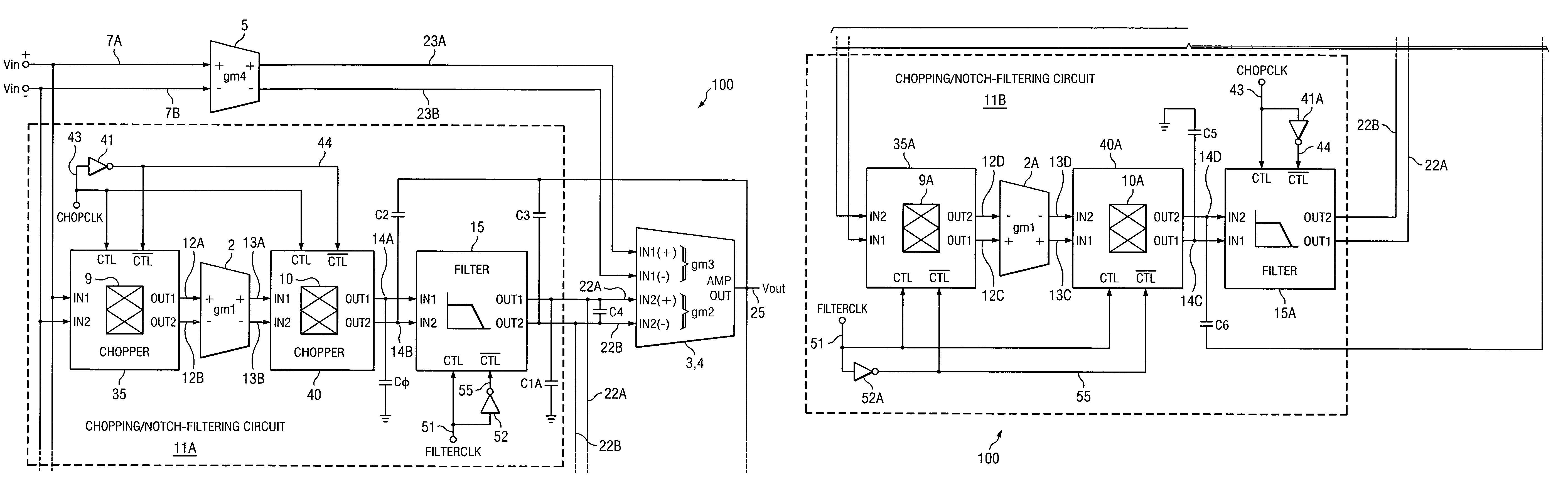
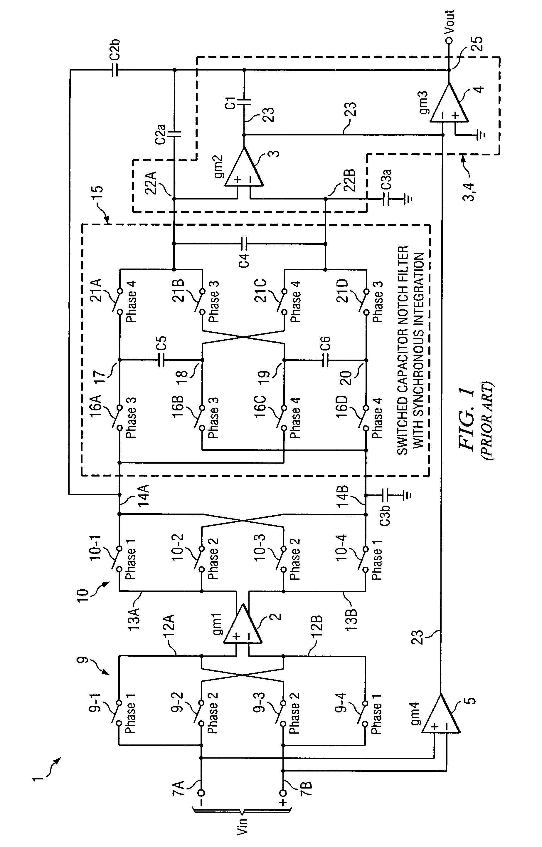
[0037]The present invention provides a dual path chopper stabilized amplifier (or one having more than dual paths) that provides improved stability and at the same time preserves the good offset, drift, and low input bias current associated with chopper stabilized amplifier performance. For example, an additional chopping stage and an additional notch filter are added in parallel with the main chopping stage 9,10 and notch filter 15 in Prior Art FIG. 3.

[0038]Referring to FIG. 4, dual path chopper stabilized amplifier 100 includes the structure shown in Prior Art FIG. 3, which includes a first chopping / notch-filtering circuit 11A. The dual path chopper stabilized amplifier 100 further includes a second chopping / notch-filtering circuit 11B. Specifically, the first chopping / notch-filtering signal path 11A includes a first input chopping circuit 35, a first differential transconductance amplifier 2, a first output chopping circuit 40, and a first notch filter 15. The second chopping / not...


PUM


Abstract

A dual path chopper-stabilized amplifier (100) includes first (11) and second (11A) chopping/notch-filtering paths, each including an input chopper (9,9A), a transconductance amplifier (2,2A), and a notch filter (15,15A). Chopping and notch filtering in the first path are controlled by first (CHOPCLK) and second (FILTERCLK) clock signals, respectively. Chopping and notch filtering in the second path are controlled by the second (FILTERCLK) and first (CHOPCLK) clock signals, respectively. Outputs of the first (15) and second (15A) switched capacitor notch filters are combined to provide an amplifier output signal (23A,B) that updates a capacitance (C4) at 4 times the frequency of the filter clock signal, to thereby improve amplifier stability without increasing clock frequency.

Description

BACKGROUND OF THE INVENTION[0001]The present invention relates generally to chopper stabilized amplifiers that include notch filters to reduce output voltage ripple, and more particularly to circuitry and methods that provide improved stability at high amplifier bandwidth.[0002]The prior art is believed to include the commonly assigned pending patent application Ser. No. 11 / 340,223 filed Jan. 26, 2006, entitled “Notch Filter for Ripple Reduction and Chopper Stabilized Amplifiers” by Rodney T. Burt and Joy Y. Zhang, and incorporated herein by reference.[0003]It is highly desirable that integrated circuit operational amplifiers have low offset voltage, low noise, low offset voltage drift, and good signal stability. Chopper stabilization and auto-zeroing are two common techniques that have been widely used to reduce amplifier offset thereof voltage and drift. Modern chopper-stabilized operational amplifiers and autozero operational amplifiers have significantly reduced, or even essenti...

Claims


Application Information

Patent Timeline
IPC IPC(8): H03F1/02
CPCH03F1/08H03F3/005H03F3/387H03F3/45475H03F2200/168H03F2203/45138
Inventor TRIFONOV, DIMITAR T.
Owner TEXAS INSTR INC
Why Eureka
Try Eureka