Portable working machine

a working machine and portability technology, applied in the field of portable working machines, can solve the problems of limiting the available space for other important components of the machine unit, affecting so as to improve the service life of the engine, reduce the cost of maintenance, and maximize the utilization of available space

Active Publication Date: 2009-04-21
HUSQVARNA AB
View PDF11 Cites 23 Cited by
  • Summary
  • Abstract
  • Description
  • Claims
  • Application Information

AI Technical Summary

Benefits of technology

[0006]According to another aspect of the invention, a front side of the engine, including the front side of the cylinder and the front side of the crankcase, as seen in a plane through the centre line and perpendicular to the axis of rotation of the tool, lies in an inclined plane which is substantially parallel with the inclined centre line of the engine cylinder. The muffler is accommodated in a space which has the substantial shape of a triangle in a cross section of said space perpendicular to said axis of rotation and located behind a disc guard, which triangle has one corner pointing upwards when the machine has an upright position, a front side facing the tool unit, a rear side, at least a top part of which is facing said inclined front sides of the cylinder block and the crankcase, and a base which faces said base line. The said space may be comparatively large and may be substantially occupied by the muffler, which allows the muffler to be afforded a sufficient size and a suitable design, which may make the muffler more efficient than is possible in existing machines of the present type, as far as sound attenuation is concerned.
[0009]Another aspect of the invention concerns the design and positioning of the fuel tank in the machine unit. According to a preferred embodiment, a rear bottom part of the muffler extends rearwards under the crank case, while a front bottom part of the fuel tank extends forwards under the crank case, where said front side of the fuel tank faces the rear side of the lower part of the muffler. According to the same embodiment, a heat insulation is provided in a gap between said front and rear sides of the fuel tank and muffler, respectively. Further, said embodiment also allows the accommodation of the crankcase above said rearward and forwards extending parts of the muffler and the fuel tank, respectively. Further the muffler, according to an aspect of the invention, has a forwards inclined side, while the fuel tank has a front, rearwards inclined size, such that the crank case can be accommodated between said inclined sides, above said rearwards and forwards projecting parts of the muffler and fuel tank, respectively. These arrangements means a very efficient utilization of available spaces for the accommodation of the muffler, the cylinder block, the crankcase and the fuel tank, which increases the space, which is available between a rear wall of the machine unit and the inclined cylinder for other functional components of the machine unit. This space, according to still another aspect of the invention, is utilized for the accommodation of the said assembly for supplying air and fuel to the engine, and it also allows improvements as far as the design of this assembly is concerned. Also at least part of the filter system, particularly a main filter, may be accommodated in said space. This means that the total filter volume can be increased thereby increasing service life of the engine, or that the machine can be made shorter and therefore easier to handle in a narrow space like a trench for a pipe to be cut. Assuming then a specific filter volume to be used. Improvements of said unit for supplying air and fuel to the engine may include any or all of the following features: placing the carburetor at a comparatively long distance from the cylinder, i.e. placing it“cold” which improves the restart of the engine in hot conditions; and employment of airhead technique, which reduces the emission of pollutions with the exhaust gas from two-stroke engines. In this connection it shall be stated that the employment of airhead technique is favourable but an option, not a prerequisite of the invention. Conventional two-stroke combustion engines may be used as well, and even four-stroke combustion engines.

Problems solved by technology

The cutting creates a lot of abrasive dust.
Without air filtration the engine will wear out in less than half an hour of operation.
This tends to limit the available space for other important components of the machine unit, such as an assembly which comprises members for supplying air and fuel to the engine, including a carburetor and a filter system for a given overall machine length.
This in turn restricts the possibilities to give the said components an appropriate design and shape.

Method used


Image

  • Portable working machine
  • Portable working machine
  • Portable working machine

Examples


Embodiment Construction

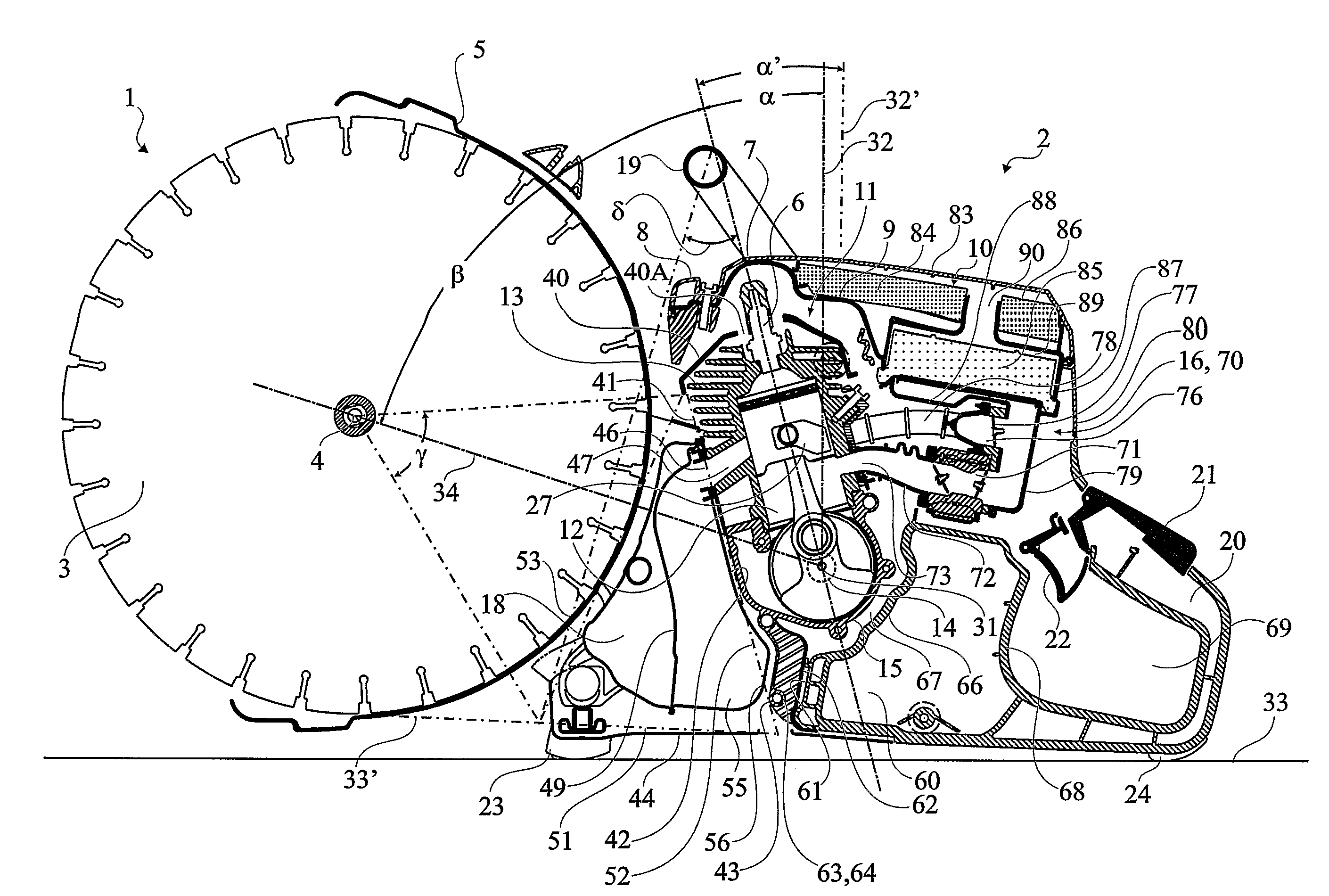
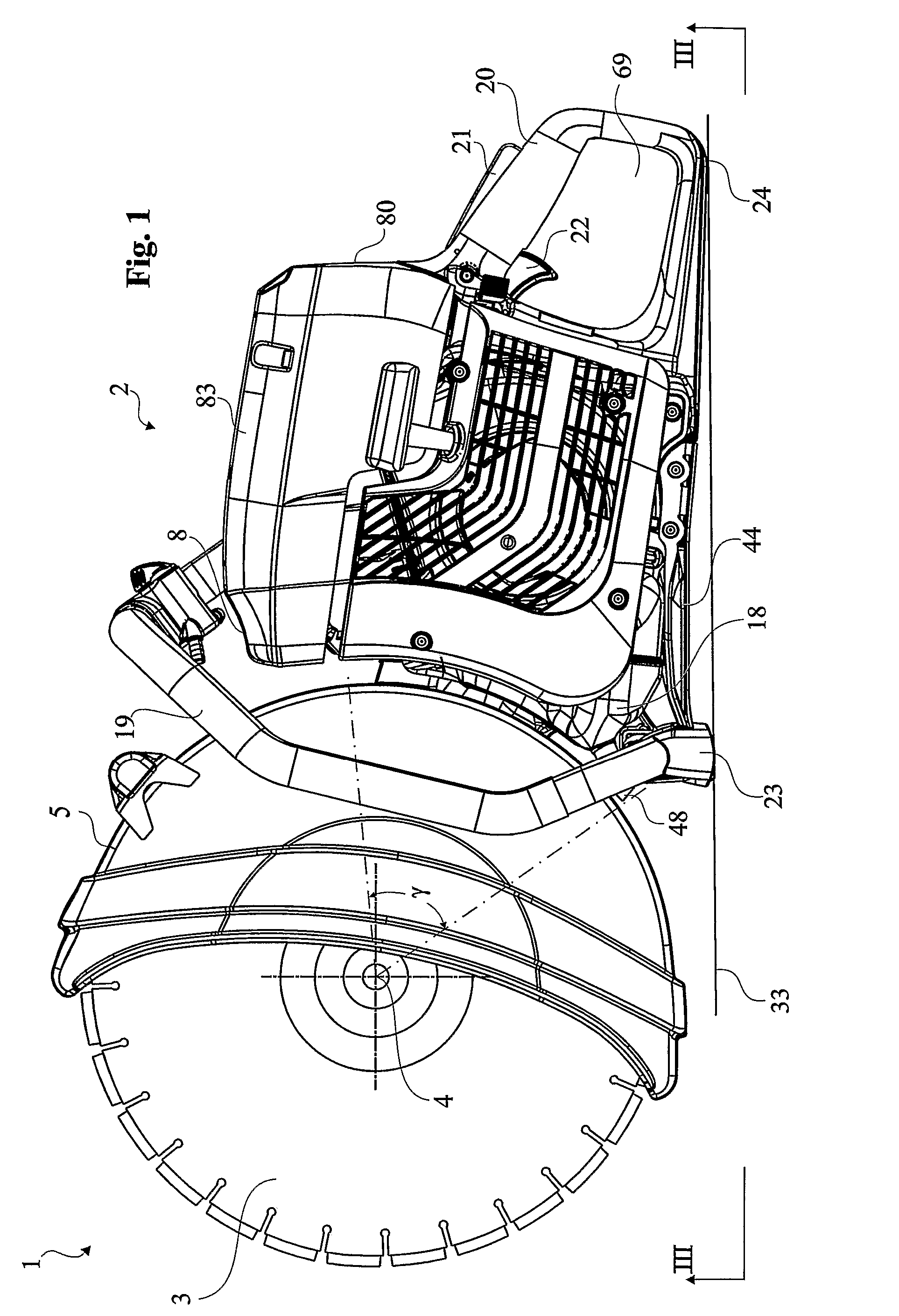
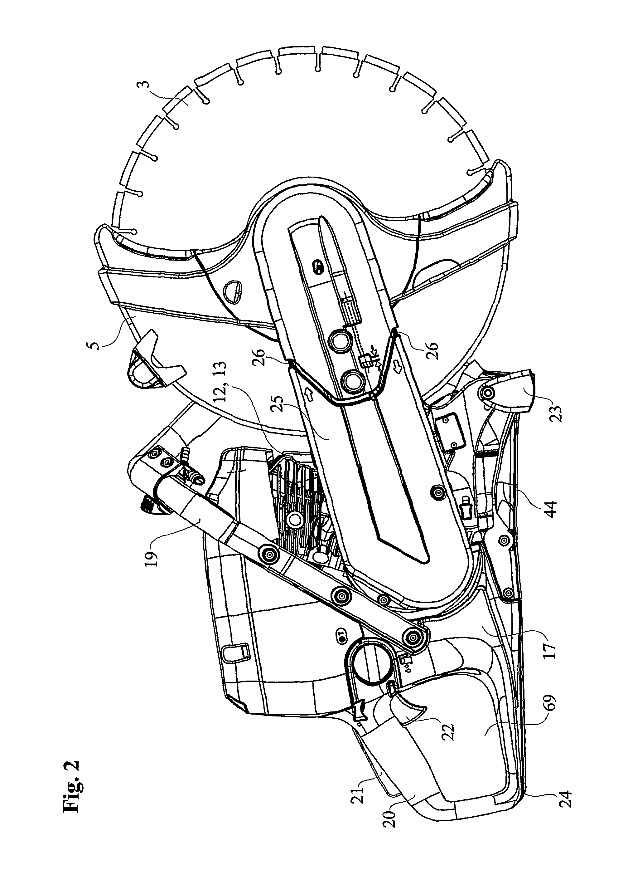
[0020]The portable working machine shown in FIG. 1-FIG. 3 comprises a tool unit 1 and a machine unit 2. A rear part of the machine is where handle 20 with controls 21, 22 is located. The tool unit 1 is provided with a circular disc shaped tool 3 in the form of a diamond equipped cutter disc, which can be rotated about an axis of rotation 4, which is horizontal in the normal upraised position of the machine, as shown in FIG. 1 and FIG. 2. A disc guard is designated 5.

[0021]The machine unit 2, FIG. 5, includes a filter system 10, a two-stroke internal combustion engine 11 with an engine cylinder 13 with a cylinder bore 12, a crankshaft 14 and a crankcase 15, an assembly 16 for supplying air and fuel to the engine, a fuel tank 17, a muffler 18, handles 19, 20, controls 21, 22, and supports 23, 24 on the underside of the machine unit 2 for allowing upright positioning of the machine on a flat ground. A tool carrier (cutter arm) 25, FIG. 2, unites the machine unit 2 and the tool unit 1. ...


PUM

PropertyMeasurementUnit
tilt angleaaaaaaaaaa

Abstract

A portable working machine comprising a tool unit (1) with a disc guard and a circular tool (3), and a machine unit (2) with a filter system (10), an internal combustion engine (11) with an engine cylinder (13) with bore (12) having a centre line (30), a crankshaft (14) and a crankcase (15), a fuel tank (17), a muffler (18) with an entrance port (46) provided in the rear side of the muffler and facing an exhaust port (47) of the cylinder, handles (19, 20) controls (21, 22) and supports (23, 24) on the underside of the machine unit for allowing upright positioning of the machine on a flat ground. The cylinder bore (12) is inclined forwards in a direction towards the tool unit, such that the centre line (30) of the cylinder bore forms a tilt angle larger than zero, in the direction, to a perpendicular to any or both of the following lines: (a) a base line (33) which is a line coinciding with a horizontal surface on which the machine is resting in an upright position, when the supports on the underside of the machine unit contact the surface, and (b) a tangential line (33′) extending from a peripheral point of the tool, on the lower part of the tool when the machine has an upright position, to the bottom side of a rear support of the machine unit.

Description

TECHNICAL FIELD[0001]The present invention relates to a portable working machine comprising a tool unit with a circular, disc-shaped tool, which can be rotated about an axis of rotation, which is horizontal in the normal upraised position of the machine, and a machine unit, which includes at least a filter system, which is at least partly accommodated in a top part of the machine unit, an internal combustion engine with an engine cylinder with bore having a centre line, a crankshaft and a crankcase, an assembly comprising members for supplying air and fuel to the engine, a fuel tank, a muffler, handles and controls, and preferably supports on the underside of the machine unit for allowing upright positioning of the machine on a flat ground, and a power transmission between the machine unit and the tool unit.BACKGROUND OF THE INVENTION[0002]Portable working machines of the above defined type are known since long. They are often used for cutting concrete and similar materials. The cut...

Claims


Application Information

Patent Timeline
Patent Type & Authority Patents(United States)
IPC IPC(8): B28D1/04B23D45/16F02B63/02
CPCB23D45/16B28D1/04F01N1/00F01N13/1888F02B63/02F01N2340/04F01N2590/06
Inventor JAKOBSSON, ANDERSKOHLER, ANDERSREUTERBERG, ANDERSSUNDBERG, NIKLAS
Owner HUSQVARNA AB
Why Eureka
Try Eureka