Indexable insert

a technology of indexable inserts and inserts, applied in the direction of cutting inserts, manufacturing tools, shaping cutters, etc., can solve the problems of reducing the rake face of the tool, and affecting the productivity of the tool

Active Publication Date: 2009-04-28
SUMITOMO ELECTRIC HARDMETAL CORP
View PDF31 Cites 14 Cited by
  • Summary
  • Abstract
  • Description
  • Claims
  • Application Information

AI Technical Summary

Benefits of technology

[0042]The indexable insert according to the present invention has excellent chip controllability in cutting of a hard material, and is applicable to wide-ranging working conditions. Also when chips flow out toward the central portion or deviate from the center of the nose R and flow out toward a portion around the outer periphery of the tool to destabilize chip outflow in outer diameter working and end face working in hardened steel cutting, for example, chips collide with the inclined part of the protrusion to be curled and parted. Thus, the indexable insert according to the present invention is also applicable to a case requiring high chip treatability, and can have a long-lived chip treatment effect. Also in cutting for carburized layer removal with extreme variation of the hardness of the work, further, the inventive indexable insert can have a long-term chip treatment effect and is applicable to wide-ranging working conditions, for solving the problems of the prior art requiring a plurality of cutting tools every tooling. In particular, the inventive indexable insert improving the surface roughness of the land part can maintain superior chip treatability, to attain a longer tool life. In addition, effective utilization of the same insert, change of feed conditions with no insert exchange etc. are further simplified.

Problems solved by technology

However, a conventional cutting tool of a cubic boron nitride sintered body is hardly provided with a chip breaker for parting chips, and hence abnormal detachment of a work or the tool or deterioration of the work surface so easily results from involution of chips during automatic operation of a machine tool that the automatic operation may be rendered impossible to inhibit improvement of productivity.
However, the cutting tool provided with the chip breaker having such a simple shape disadvantageously requires a tool provided with different right and left hands depending on tooling, a tool provided with a breaker suitable to each of outer diameter working and end face working, a tool provided with a breaker corresponding to each of cutting conditions having different feed rates or depths of cut.
In other words, the conventional tool provided with a breaker attains the effect of chip treatment only under specific cutting conditions and is unapplicable to wide-ranging working conditions, and hence a plurality of tools are disadvantageously required in response to various tooling conditions.
When the cutting tool is employed for cutting a hard work such as hardened steel in particular, however, chips are so hard that frictional resistance is increased due to the chips and a rake face of the tool is easily damaged by heat resulting from rubbing if the surface roughness of the superhard sintered body is in excess of 0.5 S. Consequently, the shape of the tool is disadvantageously changed due to progress of crater wear, to reduce the chip treatability.
In this cutting tool, however, the strength of a cutting edge is so insufficient for stable cutting that an edge frequently causes tool failure during cutting when the cutting tool is employed for cutting a hard work such as hardened steel.

Method used


Image

  • Indexable insert
  • Indexable insert
  • Indexable insert

Examples


examples

[0062]While the present invention is now more specifically described with reference to Examples and comparative examples, these Examples do not restrict the range of the present invention.

(1) Experimental Example 1

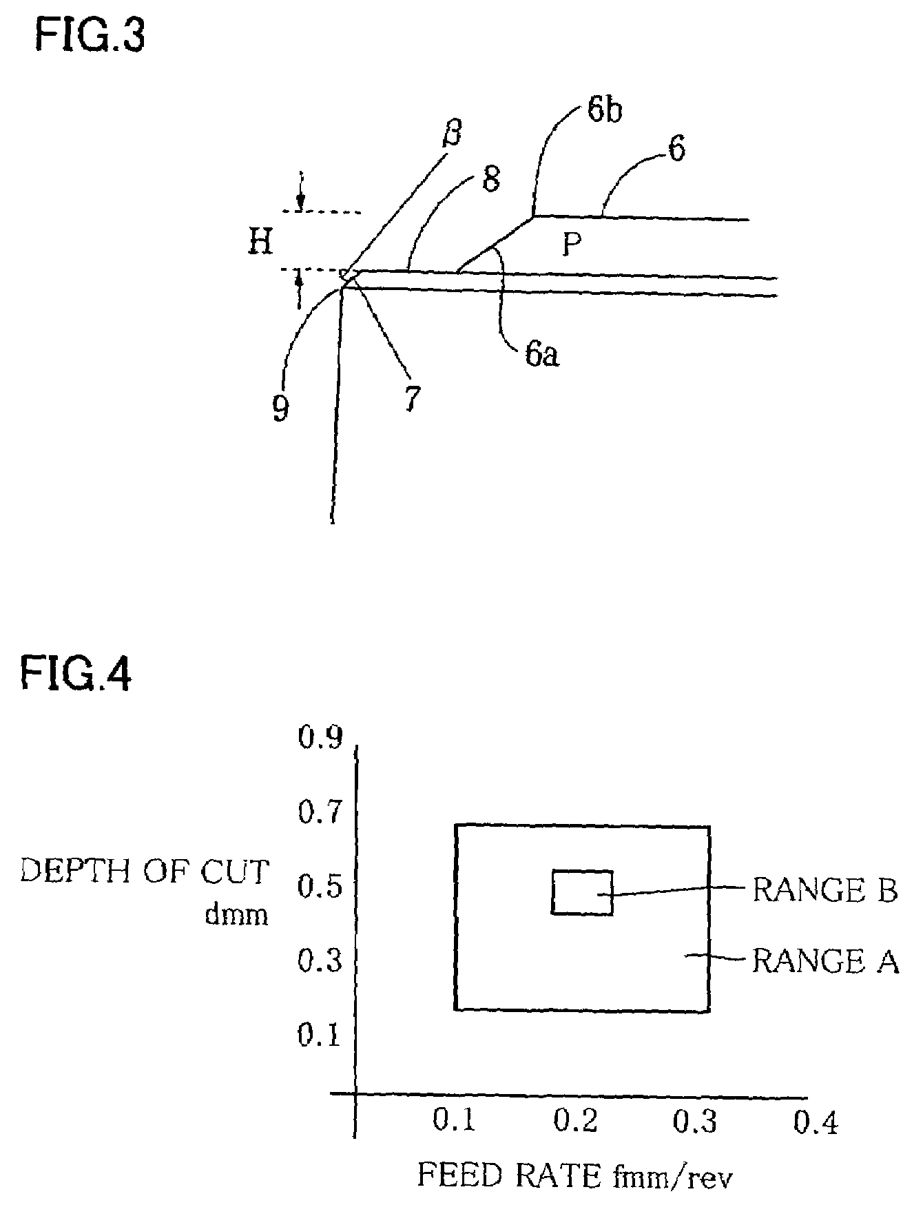
[0063]The following indexable inserts according to the present invention and conventional indexable inserts were employed for outer diameter working and end face working on SCM 415 carburized works while setting a cutting speed to V=120 m / min. and varying depths d of cut and feed rates f as shown in Tables 1 and 2. Chip states and chip lengths were obtained as to the respective cutting conditions, for evaluating chip treatability. Table 1 (outer diameter working) and Table 2 (end face working) show the results. The chip states are shown according to chip classification under INFOS.

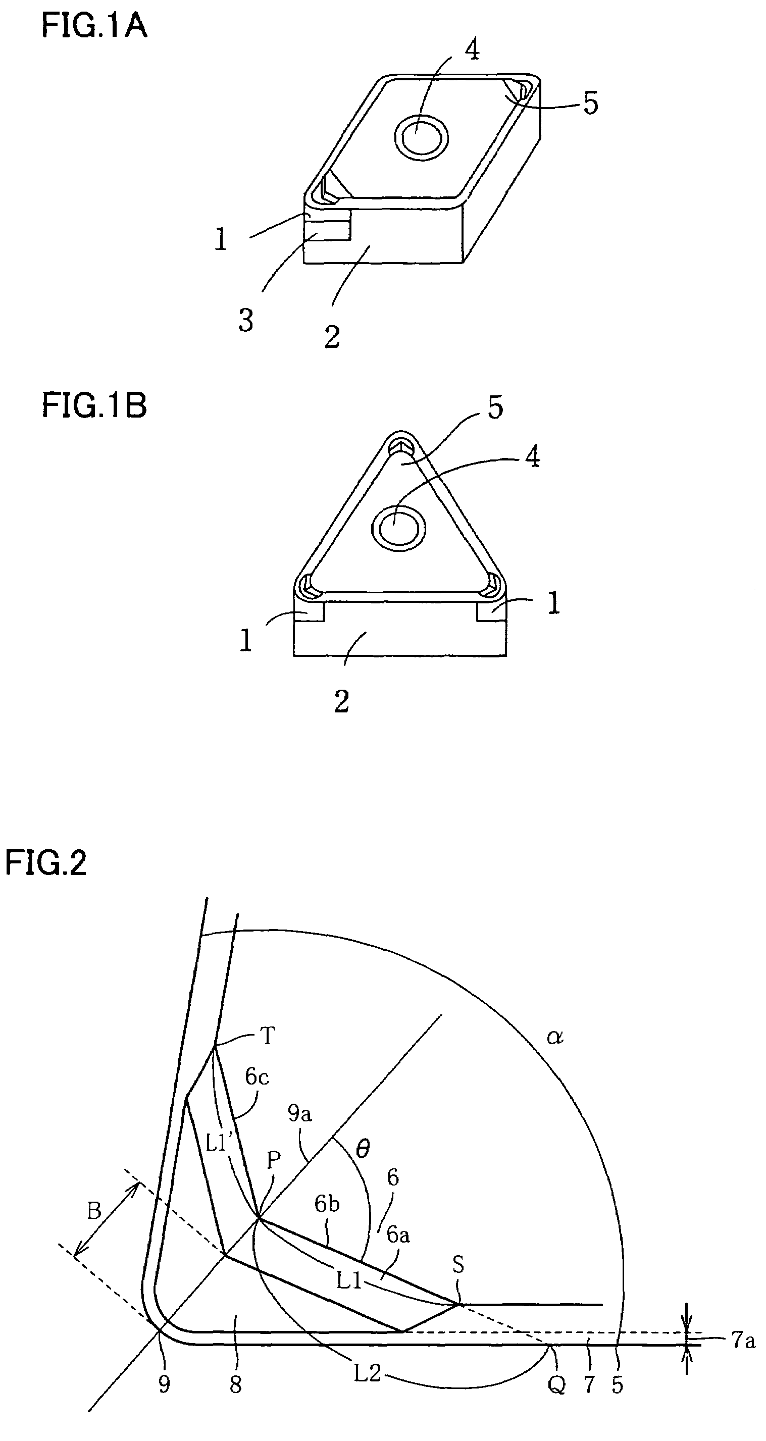
[0064]Used Inserts: CNMA 120408

[0065][Inventive Indexable Inserts]

[0066]θ=60°, L1′ / L1=1, L1 / L2=0.5, Rz JIS 94=0.3 μm (surface roughness of land parts and negative land parts adjacent to the land ...


PUM

PropertyMeasurementUnit
surface roughnessaaaaaaaaaa
angleaaaaaaaaaa

Abstract

A superhard sintered body containing cubic boron nitride is bonded to an apical angle part of a tool body having a polygonal shape, and an edge and a chip breaker are formed on the superhard sintered body. A chamfer is formed on the intersection between the upper surface and the side surface of the superhard sintered body, the chip breaker has a protrusion, and an angle θ formed by ridges on the apex of the protrusion or a tangential line at a point bisecting the ridges and a bisector for the apical angle and the ratio of the distance between a first intersection between the two ridges on the apex of the protrusion and an extreme point of the first ridge to the distance between a second intersection between a straight line passing through the first intersection and the extreme point and the outer periphery of the tool body and the first intersection are in prescribed ranges.

Description

RELATED APPLICATIONS[0001]This application is the U.S. National Phase under 35 U.S.C. § 371 of International Application No. PCT / JP2004 / 019341, filed on Dec. 24, 2004, which in turn claims the benefit of Japanese Application No. 2004-006813, filed on Jan. 14, 2004, the disclosures of which Applications are incorporated by reference herein.TECHNICAL FIELD[0002]The present invention relates to an indexable insert having excellent chip treatability, prepared by bonding a cutting edge consisting of a superhard sintered body containing cubic boron nitride to an apical angle part of a tool body.BACKGROUND ART[0003]A cutting tool of a cubic boron nitride sintered body having a cutting edge prepared by sintering fine cubic boron nitride powder with a binder exhibits excellent performance with respect to cutting of a hard iron group or cast iron.[0004]Following automation of a machine tool or introduction of unmanned operation into a production process, improvement of chip treatability has r...

Claims


Application Information

Patent Timeline
Patent Type & Authority Patents(United States)
IPC IPC(8): B23B27/22B23B27/14B23B27/20
CPCB23B27/143B23B2200/0428B23B2200/049B23B2200/28B23B2200/321Y10T407/24B23B2226/125Y10T407/235Y10T407/26Y10T407/27B23B2200/3609B23B27/22B23B27/20
Inventor OKITA, YASUHIKOKANADA, YASUYUKIFUKAYA, TOMOHIRO
Owner SUMITOMO ELECTRIC HARDMETAL CORP
Why Eureka
Try Eureka