Induction sensor

a technology of induction sensor and output, which is applied in the direction of pulse technique, non-mechanical valves, instruments, etc., can solve the problems of small measurement resolution, low voltage differential, and circuits that add much complexity for little improvement in performance, so as to improve linearity of output and improve performance. , the effect of improving the linearity of outpu

Inactive Publication Date: 2009-05-05
DIGISENSORS
View PDF31 Cites 13 Cited by
  • Summary
  • Abstract
  • Description
  • Claims
  • Application Information

AI Technical Summary

Benefits of technology

[0026]Various sensors that work on the variable reluctance principle are described. Also, sensor actuator and sensor coil shapes are described that give improved performance.
[0027]For linear position detection, a sensor coil winding technique is described that gives improved linearity of output. Also for linear position detection, a sensor actuator shape and coil actuator relationship is described that gives improved linearity of output. The material used for actuator construction is delineated.

Problems solved by technology

Because the voltage differential is small, the resolution of measurement is small and also effected by electromagnetic noise and stray capacitance in the circuit and environment.
The cause of the low voltage differential with prior art variable reluctance sensors is the result of the circuit used and also the physical characteristics of the sensors employed.
These circuits add much complexity for little improvement in performance and are seldom used.
Prior art sensors of this type suffer from the fact that the output is not linear with regard to position.
All of the prior art devices experienced various deficiencies in terms of accuracy, functionality, reliability, and cost.

Method used


Image

  • Induction sensor
  • Induction sensor
  • Induction sensor

Examples


Embodiment Construction

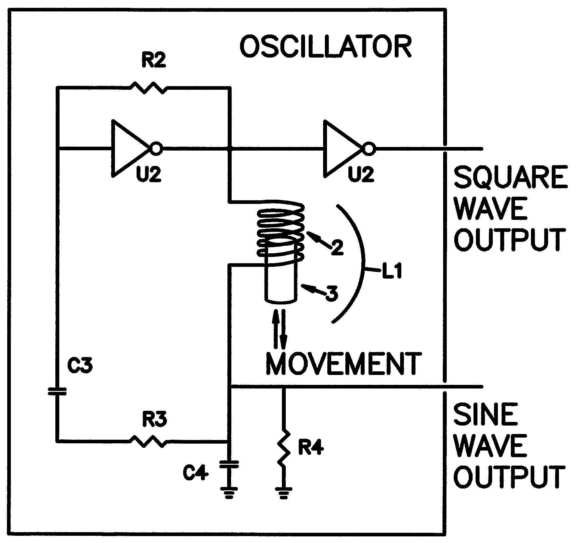
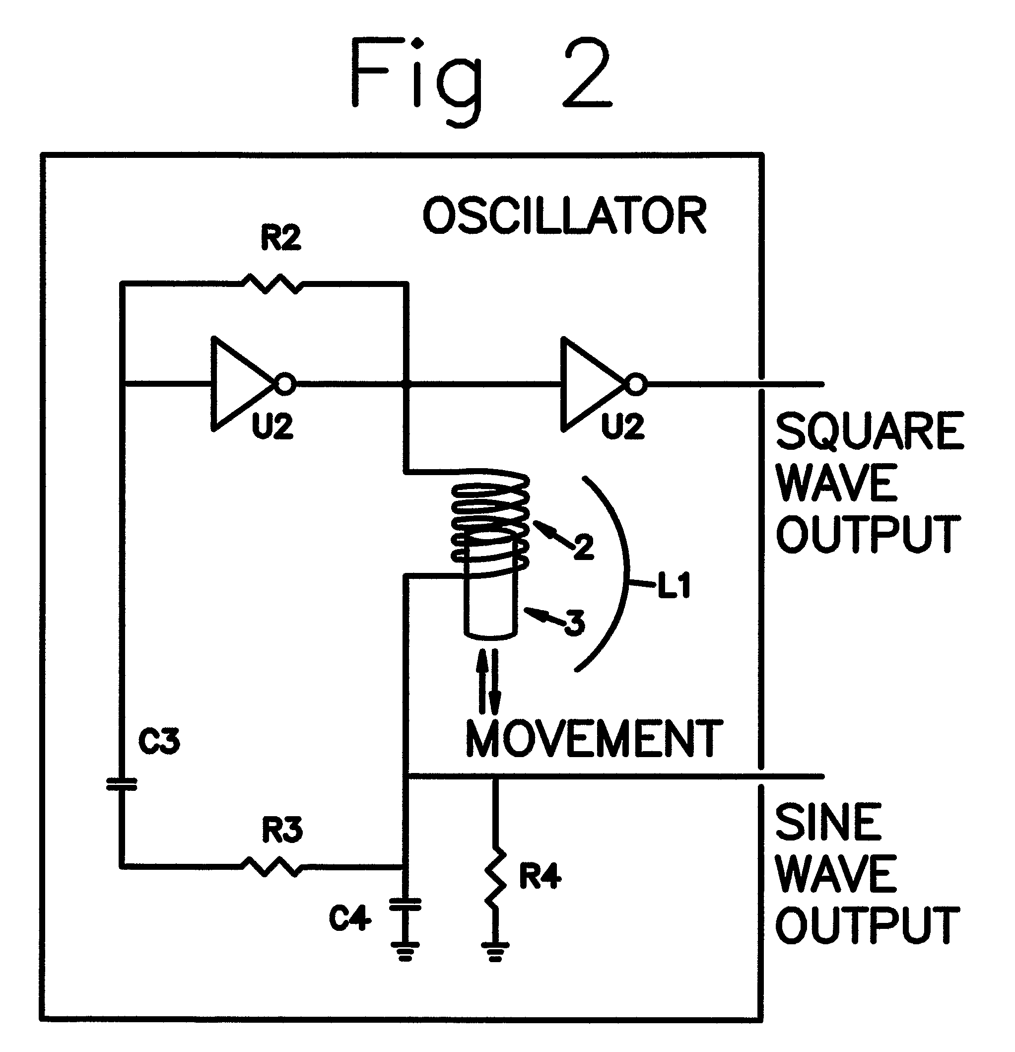
[0063]FIG. 2 shows the basic circuit of the present invention. The circuit is a tuned oscillator circuit. The tuned oscillator circuit is comprised of an amplifier (U2) and two reactive components, an inductor L1 and a capacitor C4. L1 and C4 are in series connection with C4 connected to ground (return) and L1 connected to the output of the amplifier U2. The frequency of the oscillator is:

[0064]F=12⁢π⁢LC

[0065]The amplifier U2 shown in FIG. 2 is a high speed CMOS hex inverter. The resistor R2 is used to bias the input of the amplifier to compensate for the leakage current. The resistor R3 and capacitor C3 provide the feedback path. The oscillator is AC coupled by capacitor C3 so that there is no DC voltage path through the oscillator. A transistor amplifier or operational amp will also work in place of hex inverter U2. The inductor L1 is the coil in the sensors disclosed in this paper. Two signals can be generated from the oscillator for use as output. One signal is a square wave the...


PUM


Abstract

Position sensor circuits are disclosed for use with variable reluctance sensors. Variable reluctance sensors are described for linear, angular and rotary position measurement and for acceleration measurement.

Description

CROSS-REFERENCE TO RELATED APPLICATIONS[0001]This application is a national stage filing under 35 U.S.C. 371 of International Application No. PCT / US05 / 07363, filed Mar. 07, 2005, which claims the benefit under 35 U.S.C. §119(e) of[0002]U.S. Provisional Application No. 60 / 551,199 filed Mar. 8, 2004,[0003]U.S. Provisional Application No. 60 / 566,112 filed Apr. 28, 2004,[0004]U.S. Provisional Application No. 60 / 574,414 filed May 26, 2004,[0005]U.S. Provisional Application No. 60 / 578,548 filed Jun. 10, 2004,[0006]U.S. Provisional Application No. 60 / 605,943 filed Aug. 31, 2004, and[0007]U.S. Provisional Application No. 641,225 filed Jan. 4, 2005,all of which are hereby incorporated by reference. And this application is a continuation-in-part of U.S. patent application Ser. No. 11 / 074,370, filed Mar. 07, 2005, now abandoned, the content of which is hereby incorporated by reference in its entirety.STATEMENT REGARDING FEDERALLY SPONSORED RESEARCH OR DEVELOPMENT[0008]This invention has been c...

Claims


Application Information

Patent Timeline
Patent Type & Authority Patents(United States)
IPC IPC(8): G01B7/14G01B7/30H03B1/00H03B5/00F01L9/20
CPCF01L9/04G01D5/202G01P15/11F01L9/20
Inventor TAYLORBEARD, STEVEN E.
Owner DIGISENSORS
Why Eureka
Try Eureka