Permanent magnet structure with axial access for spectroscopy applications

a permanent magnet and spectroscopy technology, applied in the field of permanent magnet structure, can solve the problems of increasing the cost of high-power electromagnets, increasing the portability of electromagnets, and inherently large and expensive magnets, and achieve the effect of eliminating or overcoming

Inactive Publication Date: 2009-05-19
MAKROCHEM
View PDF25 Cites 15 Cited by
  • Summary
  • Abstract
  • Description
  • Claims
  • Application Information

AI Technical Summary

Benefits of technology

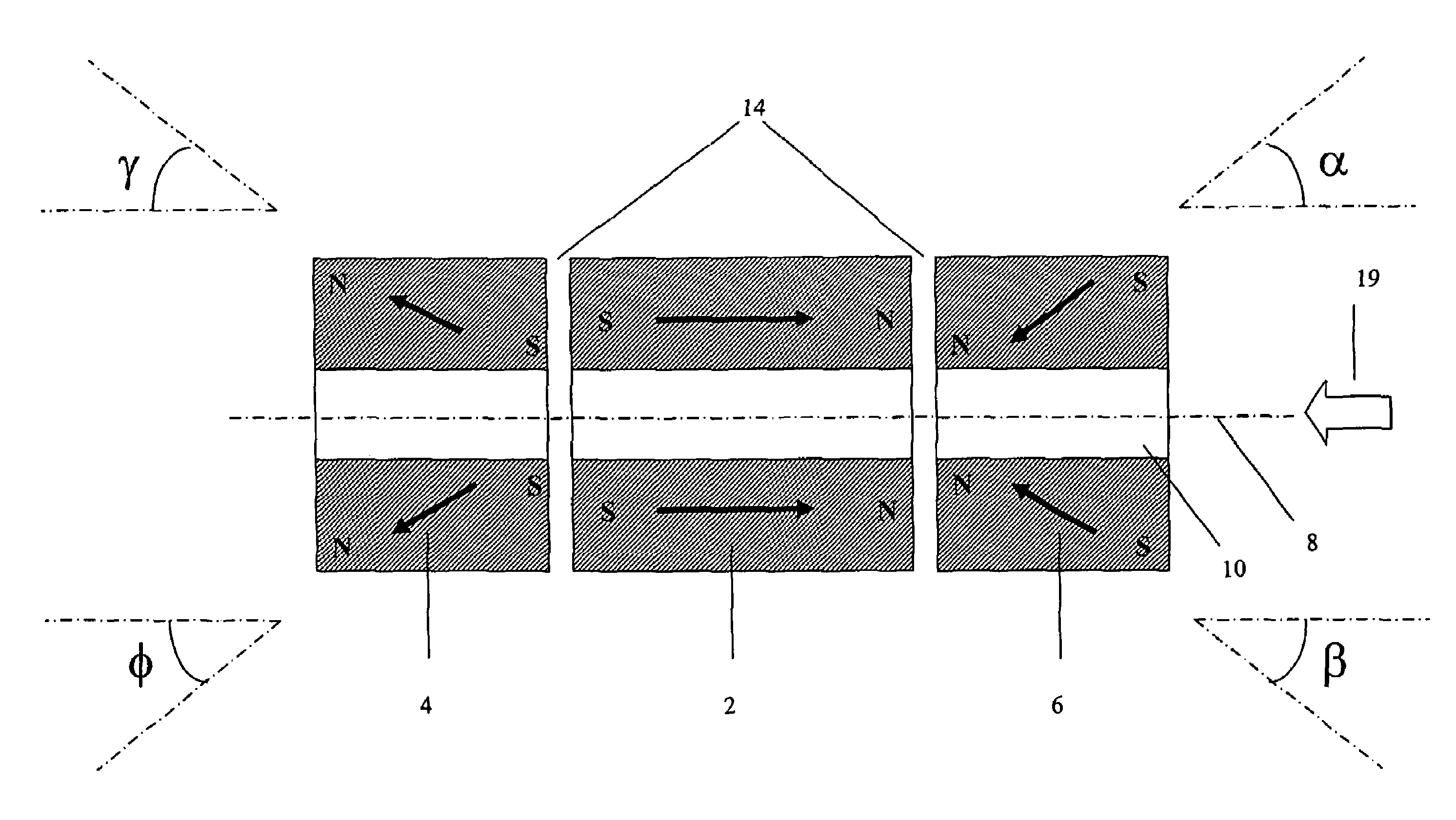
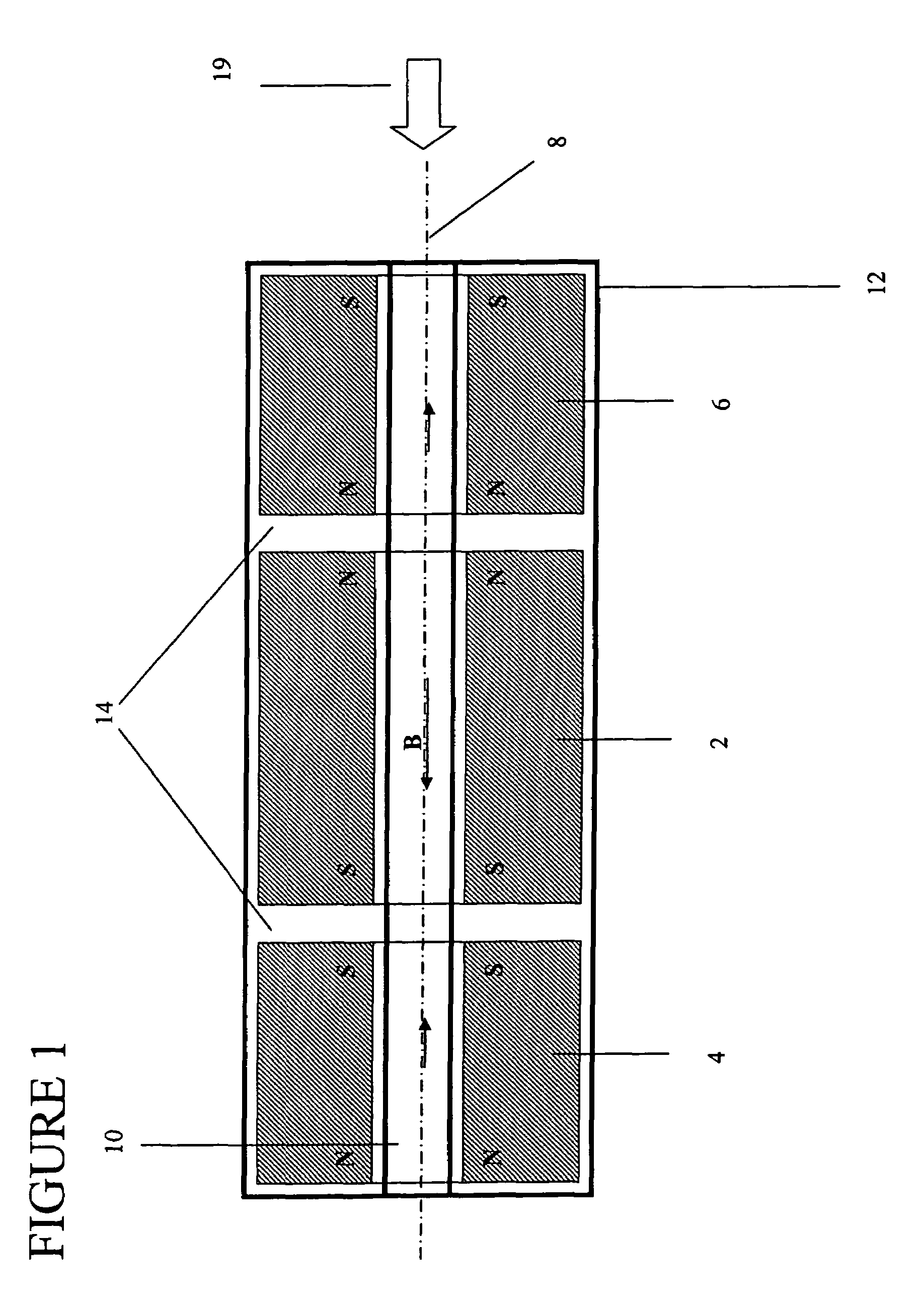
[0017]One object of present invention is to eliminate or overcome the limitations imposed on spectroscopy applications by providing homogeneous magnetic fields in large spatial volumes within magnet structures having through-holes for axial access to that working volume.
[0018]Still another object of the present invention is to provide a magnet flux source that can maximize the flux density generated per weight of magnetic material.
[0024]In various embodiments of the present invention, the hollow body flux sources can be made of magnetic materials or incorporate magnetic materials of high magnetic properties. The hollow body sources are configured to have directions of magnetization such as to reduce magnetic flux leakage from the central regions such as to focus flux density lines into a central air gap in the first or central flux source.

Problems solved by technology

Electromagnets require large power supplies for charging and superconducting solenoids require extensive cooling systems to maintain the solenoid below the requisite critical low temperature.
Liquid helium is typically used and is typically replenished periodically to cool the magnet, which makes the magnet inherently large and expensive.
Not only do these attributes increase the cost of high powered electromagnets, but such approaches also diminish, if not eliminate, the portability of electromagnets due to their large size and weight, especially those capable of generating strong magnetic fields.
Nonetheless, permanent magnets in the past have been unable to generate magnetic flux densities commensurate with electromagnets.
However, the former structures can result in bulky magnet assemblies that require large consumption of permanent magnet material to generate uniform high magnetic field, and the latter generate a uniform high magnetic field perpendicular to the direction of the axial access inside the bore of assembly constructed from ring-shape magnets.
Therefore, utilizing any of the above two structures results in (1) limited access to the central region of the homogeneous magnetic field; (2) limited space to place a device such as charged particle trap, particle (charged or neutral) detector, or NMR probe; and (3) limited capabilities to couple a charged particle trap, or a particle detector, with the charged or neutral particle transport systems when those particles are generated outside the magnet.
If, for example, FTMS trap is used as a mass spectrometry analyzer that traps charged particles along the magnetic field flux direction and the direction is perpendicular to the axis along which the charged particles move from the mass spectrometry devices or particle sources outside the magnet, there are difficulties in coupling such devices or sources with the analyzer.
The coupling will require an implementation of a mechanism to turn the particle beam by 90 degrees before injecting the ions into the FTMS trap that further restricts the size of the said trap and, therefore, limit the performance of the FTMS analyzer as described in M. V. Gorshkov, H. R. Udseth, G. A. Anderson, R. D. Smith, Eur. J. Mass Spectrom., 2002, 8, pp.
As a consequence, the mass spectrometer performance and upper limit of mass of ions that could be trapped were limited.

Method used


Image

  • Permanent magnet structure with axial access for spectroscopy applications
  • Permanent magnet structure with axial access for spectroscopy applications
  • Permanent magnet structure with axial access for spectroscopy applications

Examples


Embodiment Construction

[0037]While the invention will be described in connection with certain preferred embodiment, there is no intent to limit the present invention to those embodiments. On the contrary, all alternatives, modifications and equivalents as included within the spirit and scope of the invention are part of the present invention.

[0038]For the purpose of this invention a spectrometer can be any of mass spectrometer (MS), nuclear magnetic resonance (NMR) spectrometer, electron paramagnetic resonance (EPR) spectrometer, and magnetic resonance imaging (MRI) spectrometer, ion mobility spectrometer (IMS), or any combination thereof.

[0039]For the purpose of this invention a mass spectrometer can be any of (but not limited to) mass spectrometry of ion cyclotron resonance with or without Fourier transform to generate mass spectra, time-of-flight mass spectrometry, quadrupole mass spectrometry, and radio-frequency ion trap mass spectrometry, wherein the trap can be either three-dimensional or two-dimen...


PUM

PropertyMeasurementUnit
sizeaaaaaaaaaa
magnetic fieldsaaaaaaaaaa
sizeaaaaaaaaaa

Abstract

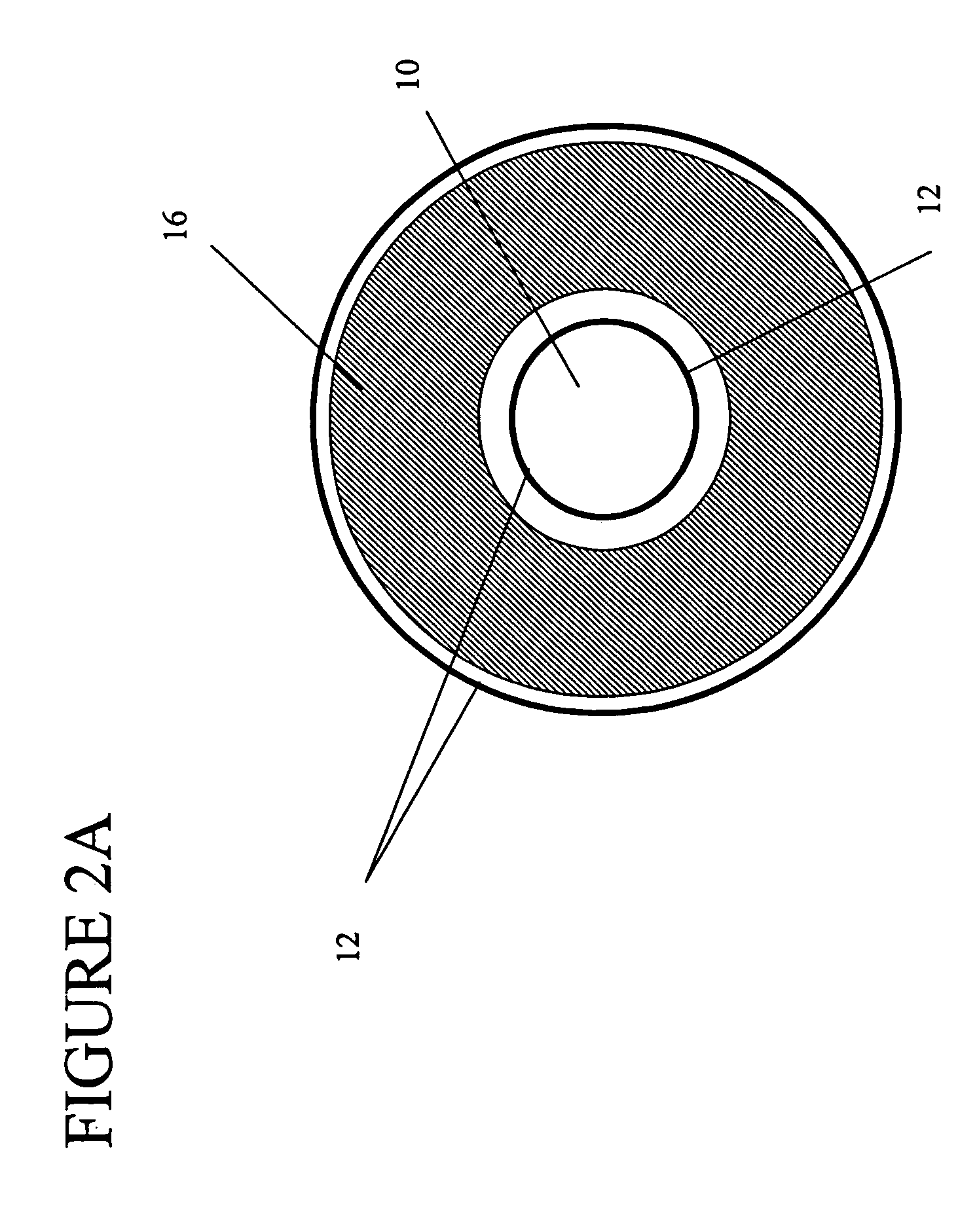
A magnet structure or instrument for spectroscopy including a plurality of magnetic flux sources disposed along a common axis. The plurality of permanent magnetic flux sources include a first magnet flux source having a first through-hole body, and include second and third magnet flux sources located respectively on opposite sides of the first magnet flux source, with at least one of the second and third magnet flux sources having a side through-hole body. Magnetic flux within the first magnet flux source is oriented to generate a first magnetic field directed along the common axis. Respective magnetic fluxes within the second and third magnet flux sources are oriented to generate second and third magnetic fields directed along the common axis, with at least one field component of either the second or third magnetic fields along the common axis inside the respective second or third magnet flux sources opposed to a direction of the first magnetic field on said common axis inside the first magnet flux source.

Description

DESCRIPTION OF THE RELATED ART[0001]1. Field of the Invention[0002]The present invention relates to magnet structures and particularly to a permanent magnet structure suitable for use in mass spectrometry (MS), nuclear magnetic resonance (NMR), electron paramagnetic resonance (EPR), and magnetic resonance imaging (MRI) spectroscopies.[0003]2. Background of the Invention[0004]Various applications utilizing magnetic fields require fields having high strengths, i.e. high flux densities, and high homogeneity of generated magnetic fields within a space volume large enough to accommodate devices and apparatuses that perform specific tasks within the intended applications.[0005]For example, in Fourier transform mass spectrometers (FTMS) as described in U.S. Pat. No. 3,937,955, issued Feb. 10, 1976; M. V. Buchanan, Ed. Fourier Transform Mass Spectrometry: Evolution, Innovation, and Applications, ACS Symp. Series, 1987, 359, pp. 205; A. G. Marshall, Adv. Mass Spectrom., 1989, 11A, p. 651; A....

Claims


Application Information

Patent Timeline
Patent Type & Authority Patents(United States)
IPC IPC(8): H01F7/02
CPCG01R33/3806G01R33/383H01F7/0278H01J49/26H01J49/38G01R33/60
Inventor GORSHKOV, MIKHAIL V.
Owner MAKROCHEM
Why Eureka
Try Eureka