
Ablative ultrasonic-cryogenic apparatus

a cryogenic apparatus and ultrasonic technology, applied in the field of ablative equipment, can solve the problems of increasing the risk of developing af, inability to induce ideal lesion, and several adverse interactions, and achieve the effect of quick inducing surface abrasion, facilitating the movement of the probe during ablation, and facilitating surgeons to control the lesion induced

Inactive Publication Date: 2009-06-02
BACOUSTICS LLC
View PDF123 Cites 145 Cited by
  • Summary
  • Abstract
  • Description
  • Claims
  • Application Information

AI Technical Summary

Benefits of technology

Enables the creation of precise, deep lesions with reduced collateral damage, improving treatment efficacy for atrial fibrillation and other arrhythmias by allowing for mechanical, ultrasonic, and cryogenic ablation, with enhanced control and potential for improved tissue healing.

Problems solved by technology

(Hurst's the heart, page 836) However, such drugs often lead to the creation of pro-arrhythmic conditions thereby resulting in the treatment of one type of arrhythmia only to create another.
(Hurst's the heart, page 833) Besides being difficult to dose, warfarin has several complications associated with its long term use.
Altering the metabolism of other drugs, warfarin is known to induce several adverse interactions with other medications commonly prescribed to elderly patients, who are at increased risk of developing AF.
Cardiac catheters employing a variety of thermal ablative energy sources have been developed, none of which are capable of inducing an ideal lesion.
Catheters utilizing radio frequency as an ablative energy source, the current gold standard, are incapable of creating an ideal lesion.
(Cummings et al., 2005) In particular, radio frequency catheters have a difficult time creating ablations through the epicardial fat surrounding the heart.
Furthermore, inducing deep lesions with radio frequency is not possible without inflicting collateral damage from surface burning and steam popping.
(Cummings et al., 2005) Furthermore, fat continues to be a significant barrier.
Although high powered lasers carry a high risk of crater formation at the site of application, low energy lasers produce lesions with a depth related to the duration of application.

Method used


Image

  • Ablative ultrasonic-cryogenic apparatus
  • Ablative ultrasonic-cryogenic apparatus
  • Ablative ultrasonic-cryogenic apparatus

Examples


Embodiment Construction

[0031]Disclosed is an ablative apparatus that may be used to treat atrial fibrillation and other arrhythmias. Preferred embodiments of the ablative apparatus are illustrated in the figures and described in detail below.

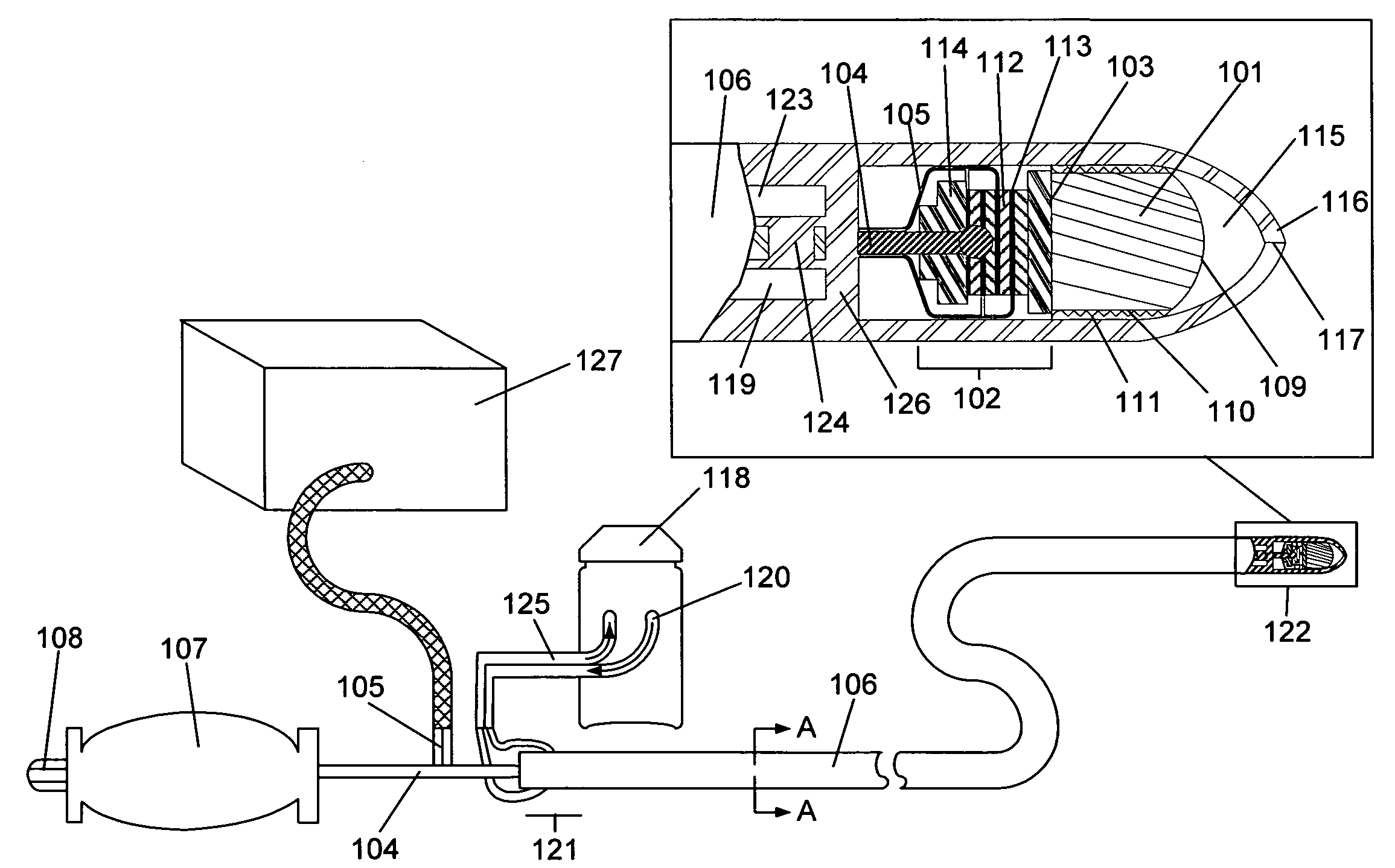
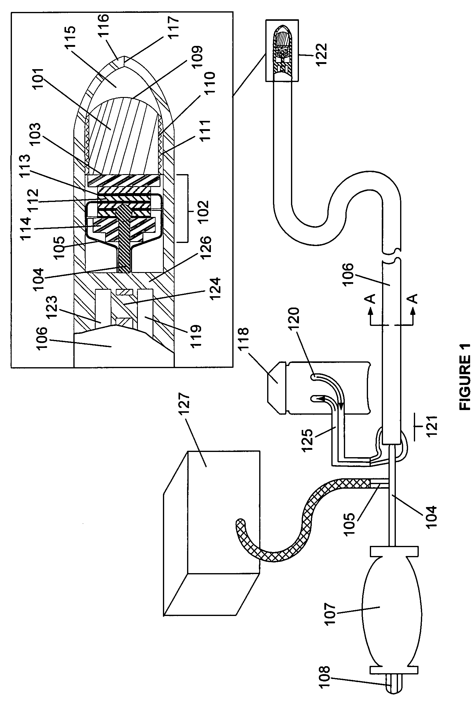
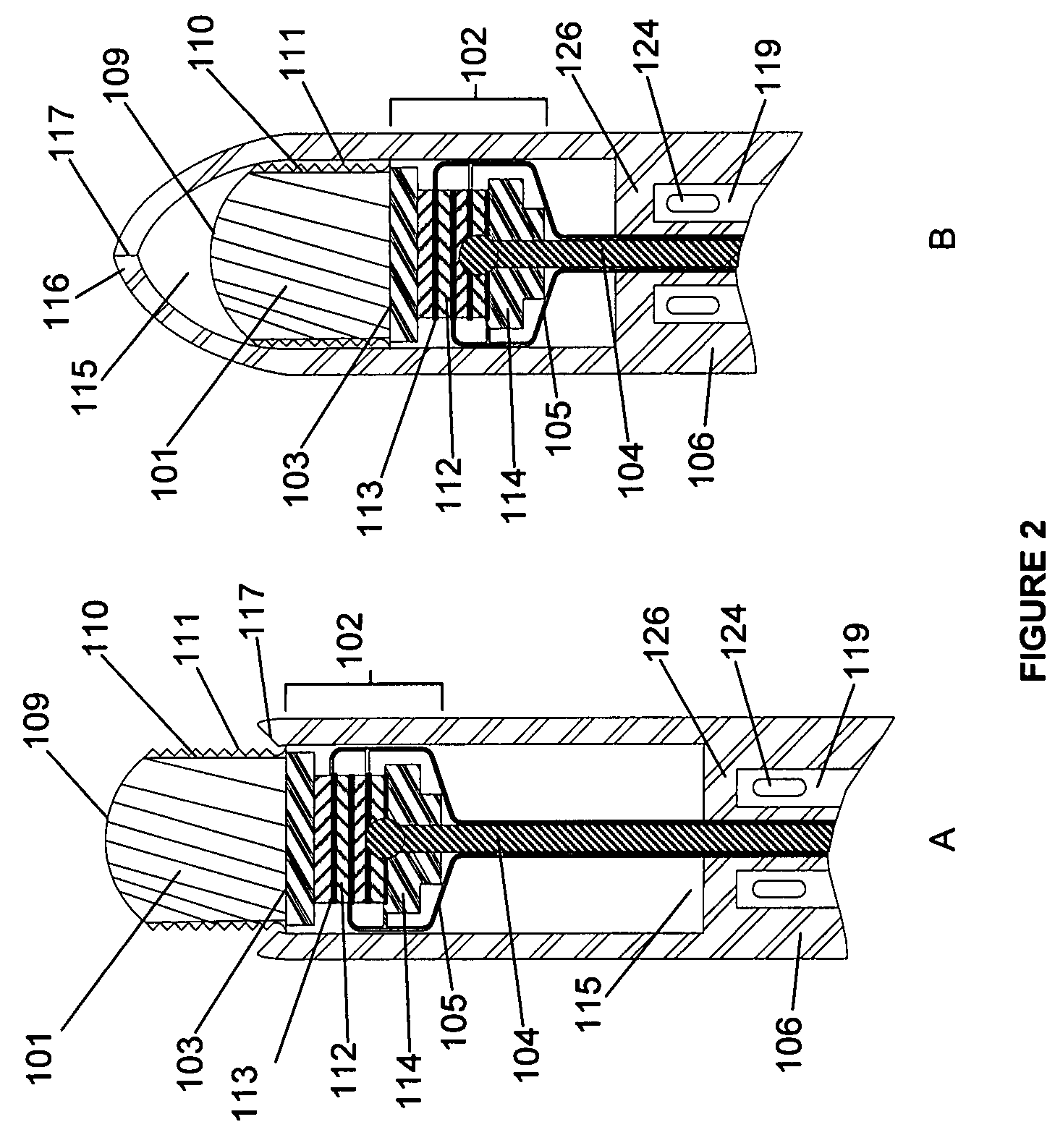
[0032]FIG. 1 depicts a possible embodiment of the ablative apparatus. The ablative apparatus comprises an ablation probe 101, a transducer 102 capable of capable of ultrasonically driving the ablation probe 101 in contact with the proximal surface 103 of ablation probe 101, a guide wire 104 secured at one end to transducer 102, electrical leads 105 running along guide wire 104 and connected to electrodes 113 capable of exposing piezo ceramic disc 112 within transducer 102 to an alternating voltage, a catheter 106 encasing ablation probe 101, transducer 102, and at least a portion of guide wire 104, and a handle 107 secured to the end of guide wire 104 opposite transducer 102. Preferably, catheter 106 is composed of a biologically compatible polymer. Handle 107 may con...


PUM


Abstract

An ablative apparatus that can be used to treat atrial fibrillation and other cardiac arrhythmias by ablating cardiac tissue is disclosed. When the distal end of the apparatus reaches the tissue to be ablated, an ablation probe driven by a transducer is vibrated. Scratching the tissue with abrasive members, the vibrating ablation probe is capable of mechanically ablating tissues. This mechanical ablation may be utilized to penetrate epicardial fat, thereby exposing the underlying myocardium. The ablative apparatus may then be used subject the exposed myocardium to mechanical ablation, cryoablation, ultrasonic ablation, and / or any combination thereof.

Description

CROSS REFERENCE TO RELATED APPLICATIONS[0001]This application is a continuation-in-part of U.S. patent application Ser. No. 11 / 463,187, filed Aug. 8, 2006, which is now abandoned.BACKGROUND OF THE INVENTION[0002]1. Field of the Invention[0003]The present invention relates to an ablative apparatus that can be used to treat atrial fibrillation and / or other cardiac arrhythmias by ablating cardiac tissue.[0004]2. Description of the Related Art[0005]Accounting for one-third of the hospitalizations for cardiac arrhythmia, atrial fibrillation (AF) is the most common arrhythmia (abnormal beating of the heart) encountered in clinical practice. (ACC / AHA / ESC Guidelines for the Management of Patients With Atrial Fibrillation) AF is a specific type of arrhythmia in which an abnormal beating of the heart originates in one of the heart's two atrium. Increasing in prevalence, an estimated 2.2 million Americans suffer from AF. (ACC / AHA / ESC Guidelines for the Management of Patients With Atrial Fibril...

Claims


Application Information

Patent Timeline
Patent Type & Authority Patents(United States)
IPC IPC(8): A61B18/18A61B18/04
CPCA61N7/022A61B18/0206A61B2017/003A61B2018/0212A61B2018/0262
Inventor BABAEV, EILAZ
Owner BACOUSTICS LLC
Learn More