Dielectric ceramic composition and electronic device

a technology of ceramics and electronic devices, applied in ceramics, fixed capacitors, electrical equipment, etc., can solve the problems of increasing harsh environment in which electronic equipment is placed, requiring use of pd, au, ag, etc., and achieves improved ir temperature dependence, reduced atmosphere, and small size

Active Publication Date: 2009-06-02
TDK CORPARATION
View PDF32 Cites 10 Cited by
  • Summary
  • Abstract
  • Description
  • Claims
  • Application Information

AI Technical Summary

Benefits of technology

[0015]An object of the present invention is to a provide a dielectric ceramic composition having a high relative dielectric constant, able to maintain the insulation resistance life, having a capacity-temperature characteristic satisfying the X8R characteristic of the EIA standard (−55 to 150° C., ΔC / C=±15% or less), enabling firing in a reducing atmosphere, and improved in IR temperature dependency. Another object of the present invention is to provide a multilayer ceramic capacitor or other electronic device using such a dielectric ceramic composition, able to realize smaller size and larger capacity, and able to meet demands for reduced thinness and size.

Problems solved by technology

Therefore, the environment in which the electronic apparatuses are placed has become increasingly harsh.
However, each of these formulations uses the highly volatile Pb, Bi, or Zn, so requires firing in the air or another oxidizing atmosphere.
For this reason, there is the problem that the internal electrodes of the capacitors cannot be made using inexpensive Ni or other base metals and require use of Pd, Au, Ag, or other expensive precious metals.
However, in each of the latter four publications, while the dielectric constant is high, the X8R characteristic is satisfied, and firing in a reducing atmosphere is possible, the IR temperature dependency from room temperature to a high temperature is poor and actual use as a product has been difficult.

Method used


Image

  • Dielectric ceramic composition and electronic device

Examples


example 1

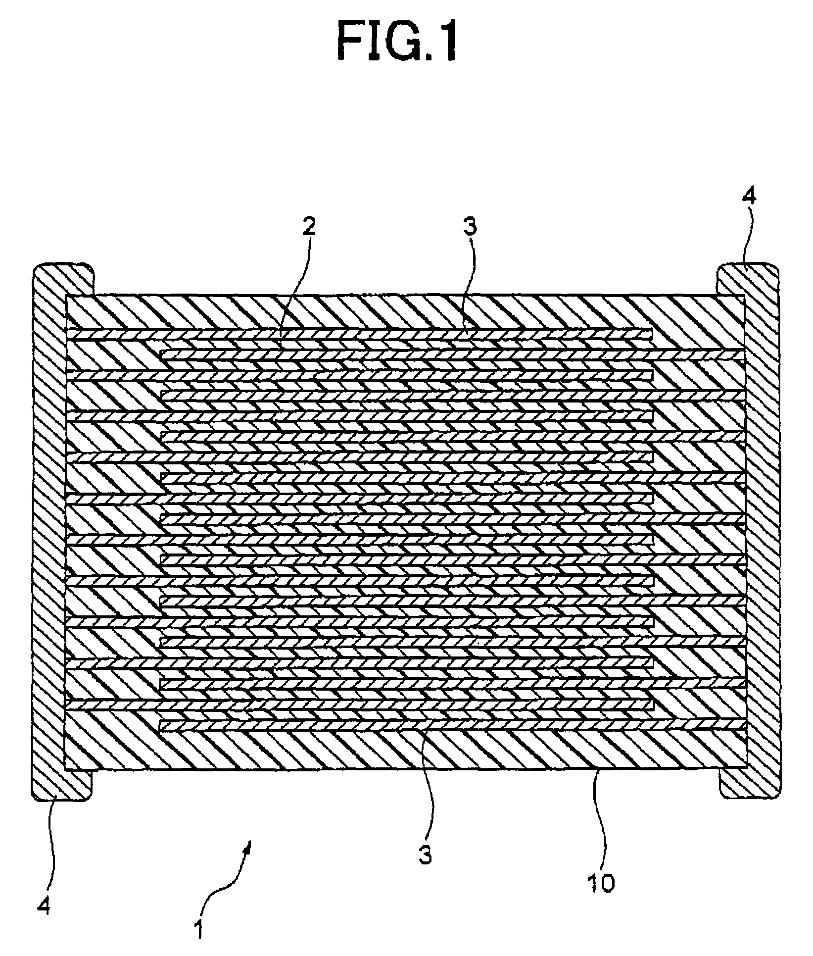
[0130]In this example, the procedure shown below was used to prepare samples of a multilayer ceramic capacitor.

[0131]Preparation of Pastes

[0132]First, starting materials for producing main ingredient materials of an average grain size of 0.1 to 1 μm (BaCO3, CaCO3, TiO2) and first to sixth sub ingredient materials were prepared. In this example, for the MgO materials and MnO materials, a carbonate (second sub ingredient: MgCO3, third sub ingredient: MnCO3) was used. As other materials, oxides (first sub ingredient: Y2O3, Dy2O3, or Ho2O3, fourth sub ingredient: Al2O3, fifth sub ingredient: V2O5, sixth sub ingredient: (Ba0.6Ca0.4)SiO3 (in the tables, described as “BCG”)) were used. Note that fifth sub ingredient (Ba0.6Ca0.4)SiO3 was produced by wet mixing BaCO3, CaCO3, and SiO2 by a ball mill for 16 hours, drying the mixture, firing it at 1150° C. in the air, and further using a ball mill to wet pulverize the result for 100 hours.

[0133]Next, the starting materials for producing the mai...

example 2

[0176]Except for changing the type and content of the fourth sub ingredient material as shown in Tables 4 to 7, the same procedure was followed as in Example 1 to prepare and evaluate different capacitor samples.

[0177]

TABLE 4Rate ofAmount oftemperatureadditionchange ofof fourthelectrostaticsubcapacityIRSampleingredient(%)X8RTC biastemperatureno.(moles)(+150° C.)characteristic(%)dependency 1*0−9.1⊚−50.9−3.48320.01−9.2⊚−49.0−2.99330.5−9.8⊚−48.2−2.97341−10.4⊚−47.1−2.78351.5−11.7⊚−44.0−2.54362−12.5⊚−41.5−2.45372.5−13.1⊚−38.1−2.45383−14.2⊚−37.8−2.37 39**3.5−15.2X−35.6−2.27 40**4−16.4X−34.1−2.25Samples with * marks are comparative examples of the present invention.Samples with ** marks are reference examples of the present invention

Note, the formulation of the main ingredient and the formulations and amounts of addition of the first to third, fifth, and sixth sub ingredients are the same as in Table 1

[0178]Fourth sub ingredient: Cr2O3

[0179]

TABLE 5Rate ofAmount oftemperatureadditionchange...


PUM

PropertyMeasurementUnit
ion radiusaaaaaaaaaa
average crystal grain sizeaaaaaaaaaa
temperatureaaaaaaaaaa

Abstract

A dielectric ceramic composition having a main ingredient including a dielectric oxide expressed by the formula {(Me1-xCax)O}m.(Zr1-yTiy)O2, where the symbol Me indicating the name of the element in said formula is at least one of Sr, Mg, and Ba and where the symbols m, x, and y indicating the molar ratios of the formulation in the formula are in relationships of 0.995≦m≦1.020, 0<x≦0.15, and 0≦y≦1.00, a first sub ingredient including an oxide of R (where R is a rare earth element), a second sub ingredient including an oxide of Mg, and a third sub ingredient including an oxide of Mn, wherein the ratios of the sub ingredients with respect to 100 moles of the main ingredient are first sub ingredient: 0.1 to 6 moles (value converted to oxide of R), second sub ingredient: 0.1 to 5 moles (value converted to oxide of Mg), and third sub ingredient: 0.1 to 2.5 moles (value converted to oxide of Mn), said dielectric ceramic composition further having as a fourth sub ingredient an oxide of A (where A is at least one type of element selected from the group of anionic elements having an effective ion radius at the time of hexacoordination of 0.065 nm to 0.085 nm).

Description

BACKGROUND OF THE INVENTION[0001]1. Field of the Invention[0002]The present invention relates to a dielectric ceramic composition having reduction resistance and a multilayer ceramic capacitor or electronic device using such a dielectric ceramic composition.[0003]2. Description of the Related Art[0004]An electronic device constituted by a multilayer ceramic capacitor is required to be high in relative dielectric constant, long in insulation resistance IR life, and good in DC bias characteristic (little change of relative dielectric constant along with time) and also good in temperature characteristics. In particular, depending on the application, it is required to have flat temperature characteristics under stringent conditions. In recent years, multilayer ceramic capacitors have come to be used in engine electronic control units (ECU), crank angle sensors, antilock braking system (ABS) modules, or other various types of electronic apparatuses mounted in automotive engine compartmen...

Claims


Application Information

Patent Timeline
Patent Type & Authority Patents(United States)
IPC IPC(8): C04B35/465C04B35/468C04B35/49
CPCB32B18/00C04B35/4682C04B35/62665C04B35/62685C04B35/638C04B35/64H01B3/12H01G4/1245B32B2311/22C04B2235/3201C04B2235/3206C04B2235/3208C04B2235/3215C04B2235/3217C04B2235/3224C04B2235/3225C04B2235/3241C04B2235/3262C04B2235/3286C04B2235/3287C04B2235/3418C04B2235/3436C04B2235/3454C04B2235/6582C04B2235/6584C04B2235/6588C04B2235/663C04B2235/785C04B2237/346C04B2237/405C04B2237/704C04B35/01C04B35/49C04B35/03
Inventor ITO, KAZUSHIGESATO, AKIRAMURASE, TAKU
Owner TDK CORPARATION
Why Eureka
Try Eureka