Supercharge Your Innovation With Domain-Expert AI Agents!

On-chip tunable artificial tank circuit

a tank circuit and artificial tank technology, applied in the field of tuned circuits, can solve the problems of low performance of inductors, difficult to minimize, and noise in electrical circuits, and achieve the effects of reducing manufacturing costs, reducing noise, and reducing on-chip layout area

Inactive Publication Date: 2009-06-02
AHMED ABDULHAKIM +1
View PDF2 Cites 1 Cited by
  • Summary
  • Abstract
  • Description
  • Claims
  • Application Information

AI Technical Summary

Benefits of technology

The artificial tank circuit achieves a voltage gain greater than 20 dB and minimizes on-chip layout area, enabling more efficient and cost-effective high-frequency operation while maintaining low noise figures and reducing the size of the tuned circuit to about one-fiftieth of its original size.

Problems solved by technology

Noise in electrical circuits, which is mainly caused by the nature of the semiconductors used, is a hindrance to the incoming signals because it interferes in the demodulation of the signals in the back-end of a radio.
Since the noise is a natural phenomenon, it is not easy to minimize, except by filtering out the part of the incoming electro-magnetic spectrum that is not occupied by the signal, and by ensuring that maximum power transfer occurs between the antenna and the input of the front-end of a radio.
Further, inductors have low performance at higher frequencies (about 3 GHz) and therefore it becomes economically inefficient to use inductors at those frequencies in integrated circuits (ICs).
This energy cannot be stored perfectly because of the series and parallel resistances in the inductor and capacitor in the tank.
Thus there is an effect of loss in the stored energy.
However the storage results in a large voltage swing required for amplification.
However, even these active inductors break down at frequencies higher than 10 GHz because of the parasitic capacitances intrinsic to active devices like MOSFETs and BJTs, and they work at frequencies below 3 GHz.
At lower frequencies, the capacitor in the LC-tank is usually too large to be put on an IC, so that it has to be put off-chip.

Method used


Image

  • On-chip tunable artificial tank circuit
  • On-chip tunable artificial tank circuit
  • On-chip tunable artificial tank circuit

Examples


Embodiment Construction

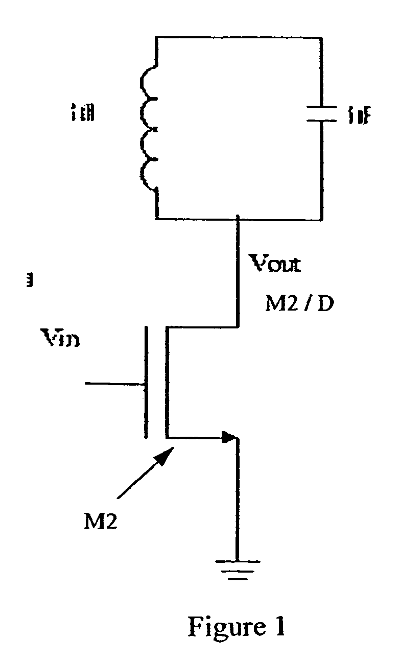
[0054]The perfect ideal LC-tank behaves like an oscillator or a resonator because it oscillates indefinitely once a certain amount of energy is put into it via an initial current or voltage. Real LC-resonators do not store energy indefinitely: they have loss through parallel and series parasitic resistances in the inductor and the capacitor. The equivalent resistance parallel to the LC-tank is the result of two parallel resistances: the intrinsic parallel resistance of the LC-tank and the output resistance of the amplifying transistor. This is what causes the loss in the energy of the tank. In short, an LC-tank used as the load impedance for an amplifying transistor oscillates at a particular frequency when an input signal is present, and does not oscillate when there is no input signal (for stability).

[0055]Using a similar concept for the artificial tank, a device that is an oscillator by nature but does not oscillate without an input signal is used, for stability purposes. In elec...


PUM


Abstract

Disclosed is a tuned circuit tuned to an input signal having a predetermined radio frequency, the tuned circuit comprising a tank circuit having a loaded ring oscillator circuit with a resonant frequency corresponding to said radio frequency. The tank circuit is configured for a predetermined frequency that the tuned circuit is designed for. In the case wherein the tuned circuit is in CMOS 0.18 μm technology, the tuned circuit is configured for a frequency of up to 7 GHz. The tank circuit may be in the form of an integrated circuit having a size of not more than 200 μm by 200 μm. The tank circuit may form part of a low-noise amplifier or part of a mixer.

Description

FIELD OF THE INVENTION[0001]The present invention relates to tuned circuits, such as tuned amplifiers or mixers. More specifically, the present invention relates to an on-chip artificial tank circuit usable in a tuned low-noise amplifier operable at high frequencies without the use of an inductor.BACKGROUND OF THE INVENTION[0002]Noise in electrical circuits, which is mainly caused by the nature of the semiconductors used, is a hindrance to the incoming signals because it interferes in the demodulation of the signals in the back-end of a radio. It is important to suppress all noise sources at the beginning or the input of the receiver-chain so that the noise does not get amplified by the first circuit.[0003]Since the noise is a natural phenomenon, it is not easy to minimize, except by filtering out the part of the incoming electro-magnetic spectrum that is not occupied by the signal, and by ensuring that maximum power transfer occurs between the antenna and the input of the front-end...

Claims


Application Information

Patent Timeline
Patent Type & Authority Patents(United States)
IPC IPC(8): H03B27/00
CPCH03F1/02H03F1/26H03F1/565H03F3/191H03F3/195H03F3/45183H03J5/244H03F2200/225H03F2200/294H03F2200/372H03F2200/391
Inventor AHMED, ABDULHAKIMWIGHT, JAMES STUART
Owner AHMED ABDULHAKIM
Features
  • R&D
  • Intellectual Property
  • Life Sciences
  • Materials
  • Tech Scout
  • Unparalleled Data Quality
  • Higher Quality Content
  • 60% Fewer Hallucinations
Learn More