
Sintered electrode for cold cathode tube, cold cathode tube comprising this sintered electrode for cold cathode tube, and liquid crystal display device

a cold cathode tube and sintered electrode technology, which is applied in the direction of instruments, machines/engines, transportation and packaging, etc., can solve the problems of deteriorating the service life of the lamp, unable to utilize mercury in luminescence, etc., and achieves low operating voltage, large surface area, and suppression of sputtering during operation

Active Publication Date: 2009-06-23
KK TOSHIBA +1
View PDF6 Cites 3 Cited by
  • Summary
  • Abstract
  • Description
  • Claims
  • Application Information

AI Technical Summary

Benefits of technology

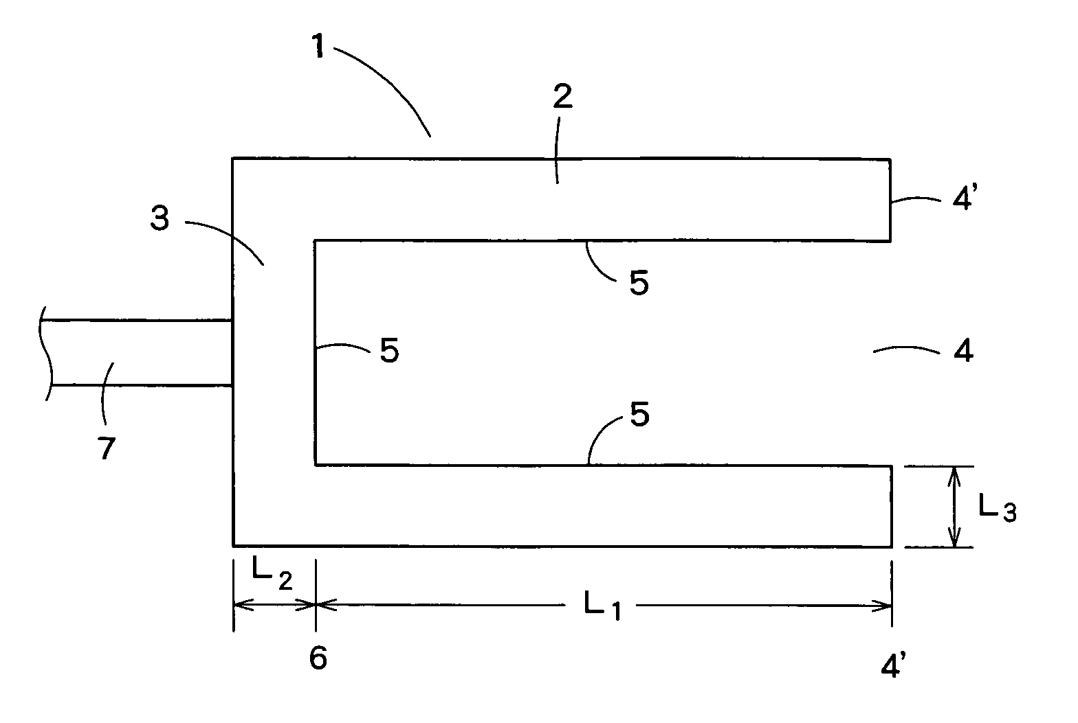
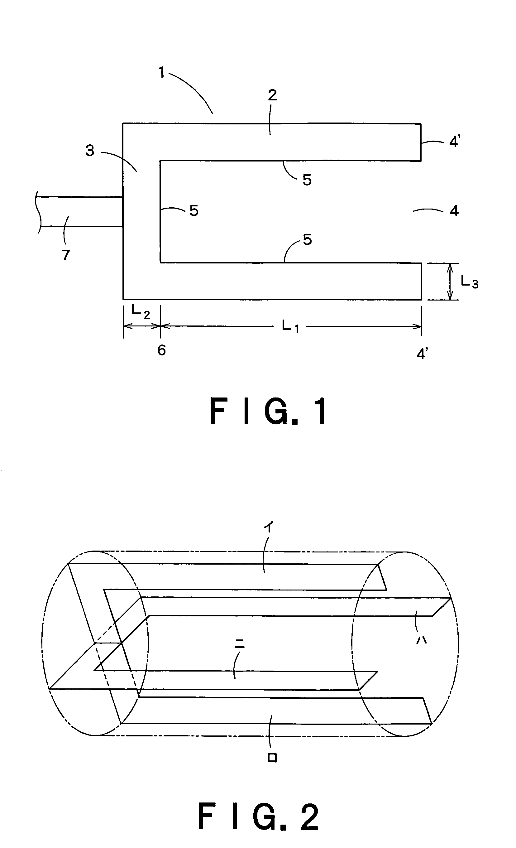
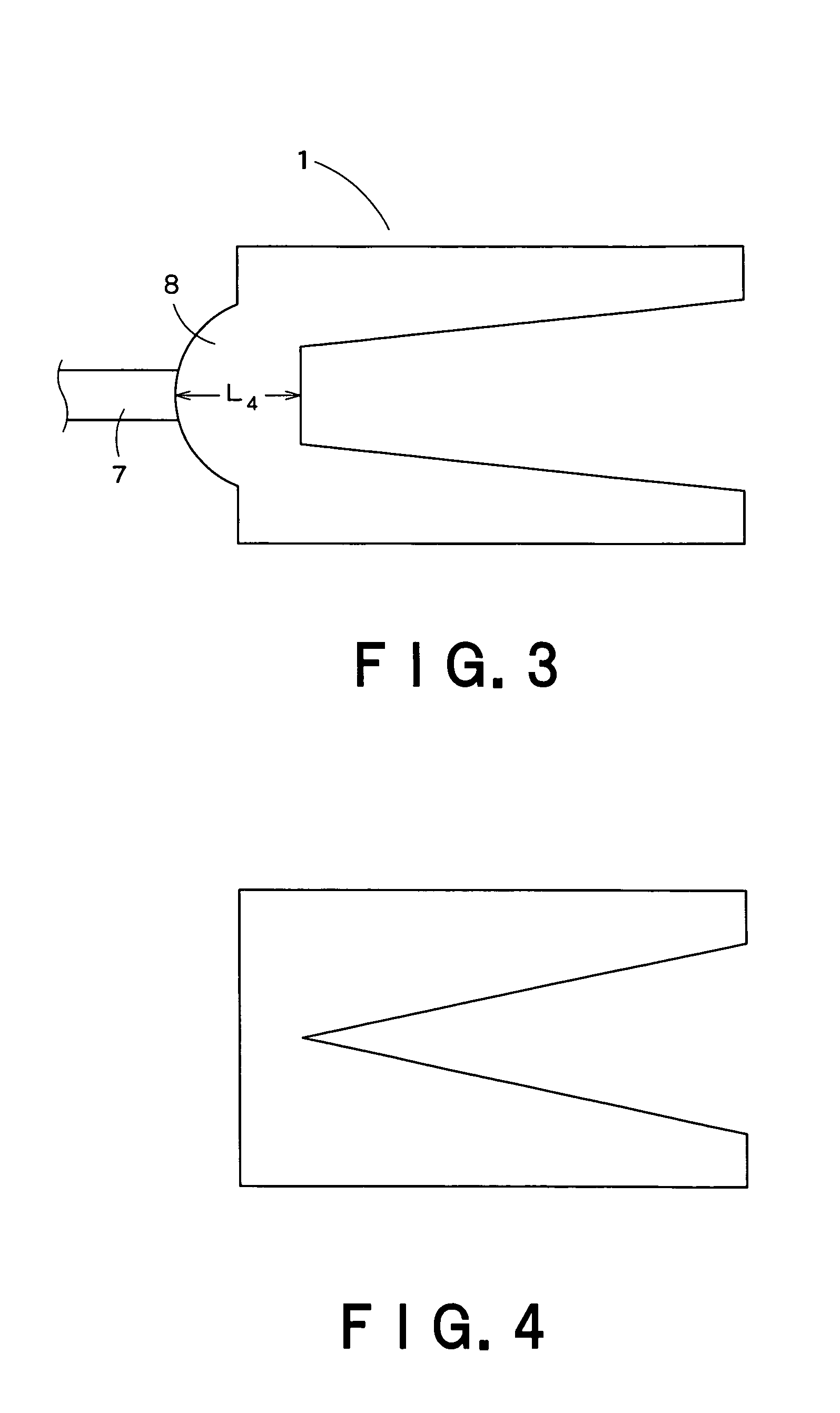
[0029]In the sintered electrode for a cold cathode tube according to the present invention, since the surface roughness (Sm) of the inner surface of the electrode is not more than 100 μm, the surface area is large and sputtering during operation can be suppressed. Therefore, the sintered electrode for a cold cathode tube according to the present invention can provide a long-service life cold cathode tube that is low in operating voltage and can significantly suppress mercury consumption.
[0030]In the sintered electrode for a cold cathode tube according to the present invention, the amount of the electrode scattered material produced by sputtering is reduced, and illuminance lowering caused by the formation of an amalgam of this scattered material and mercury, and illuminance lowering caused by mercury consumption can be effectively prevented, whereby a high-luminance, high-efficiency and long-service file cold cathode tube can be provided.
[0031]Further, for the sintered electrode for a cold cathode tube according to the present invention, the mass productivity is better than that of the conventional electrode produced by drawing from a plate material, and, thus, the sintered electrode for a cold cathode tube according to the present invention can be produced at low cost.
[0032]In particular, when the sintered electrode for a cold cathode tube according to the present invention is formed of a sinter of a high-melting metal containing a rare earth element (R)-carbon (C)-oxygen (O) compound, the cathode voltage drop can be lowered to a very low level. Therefore, the sintered electrode for a cold cathode tube according to the present invention can provide a long-service life cold cathode tube that the operating voltage is further low and the consumption of mercury is significantly suppressed. In the sintered electrode for a cold cathode tube formed of the specific rare earth compound-containing sinter, the recrystallization of a sinter structure under welding conditions has been suppressed. Therefore, in the present invention, high-voltage welding conditions, which cannot be substantially adopted in conventional electrodes produced by conventional drawing, can be adopted. A sintered electrode for a cold cathode tube having a higher lead wire weld strength than the conventional sintered electrode can easily be prepared.
[0033]When the sintered electrode for a cold cathode tube according to the present invention is such that, in a section perpendicular to the longitudinal axis direction of the sintered electrode for a cold cathode tube, the inner wall surface of the cylindrical side wall part is in a concave-convex form, the cathode voltage drop further lowered. Therefore, this sintered electrode for a cold cathode tube can provide a long-service life cold cathode tube that the operating voltage is lower and the amount of mercury consumption has been significantly suppressed.
[0034]So far as the present inventors know, neither focusing on the surface properties of the sintered electrode for a cold cathode tube nor any study on the relationship between the surface properties of the sintered electrode and the properties of the cold cathode tube has been made in the prior art. Therefore, it is surprising that a cold cathode tube having low operating voltage and significantly suppressed consumption of mercury can be provided by focusing on the surface properties of the sintered electrode, for a cold cathode tube, particularly surface properties of the inner surface of the sintered electrode for a cold cathode tube, and regulation of the surface roughness (Sm) in a specific range.

Problems solved by technology

This Ni (nickel) electrode, however, is disadvantageous in that a cathode drop voltage necessary for electron emission from the electrode to a discharge space is relatively high and, in addition, the occurrence of the phenomenon of the so-called “sputtering” is likely to deteriorate the service life of the lamp.
Mercury is introduced into the sputtering layer formed by the sputtering phenomenon, making it impossible to utilize mercury in luminescence.

Method used


Image

  • Sintered electrode for cold cathode tube, cold cathode tube comprising this sintered electrode for cold cathode tube, and liquid crystal display device
  • Sintered electrode for cold cathode tube, cold cathode tube comprising this sintered electrode for cold cathode tube, and liquid crystal display device
  • Sintered electrode for cold cathode tube, cold cathode tube comprising this sintered electrode for cold cathode tube, and liquid crystal display device

Examples


examples 111 to 143

[0167]Sintered electrodes for a cold cathode tube, which comprise an Mo sinter containing the composition of Example 59 (2% La—O—C compound (O2 content 0.4% by mass, C content 50 ppm) and has a corrugated shape as shown in FIG. 11 on the inner wall of the cylindrical side wall part, were prepared to provide a plurality of sintered electrodes for a cold cathode tube as shown in Table 8 (for all the electrodes, the outer diameter distance a is 0.085 mm).

[0168]Each electrode was incorporated in a cold cathode tube in the same manner as in Example 59, and the properties thereof were evaluated in the same manner as in Example 59.

[0169]The results were as described in Table 8

[0170]

TABLE 82% La—O—C sinter (O2 0.4 wt %, C 50 ppm), a = 0.085 mmDischargeExample No.b / ac / bvoltage, VExample 1110.951.0110Example 1120.960.9110Example 1130.950.96110Example 1140.950.95105Example 1150.950.85104Example 1160.950.695Example 1170.950.5282Example 1180.950.580Example 1190.950.4575Example 1200.71.0113Exampl...

example 144

[0171]For the electrodes of Example 60 and Comparative Example 34, the weld strength was measured. For the weld strength, the electrode was welded to an Mo lead of 0.8 mm in diameter×2.6 mm through a kovar foil of 1.0 mm in diameter×0.1 mm in length, and welding was carried out using a direct current of 500 A×30 ms. For each of the example and the comparative example, 10 assemblies were prepared. These assemblies were subjected to a tensile test at a speed of 10 mm / min (FIG. 10), and the weld strength values were compared. The results are shown in Table 9.

[0172]

TABLE 9Example 144n numberComparative Example 34(Example 60)12924292312501327353243315415370519636148573315008351439938055110 370472Average337497

[0173]As is apparent from Table 9, the sintered electrode in the example of the present invention has a high strength of joining to the lead wire.


PUM

PropertyMeasurementUnit
surface roughnessaaaaaaaaaa
thicknessaaaaaaaaaa
thicknessaaaaaaaaaa

Abstract

There are provided (1) a sintered electrode for a cold cathode tube, comprising a cylindrical side wall part, a bottom part provided at one end of the side wall part, and an opening provided at another end of the side wall part, characterized in that the surface roughness (Sm) of the inner surface of the electrode is not more than 100 μm, (2) a cold cathode tube characterized by comprising: a hollow tubular light transparent bulb into which a discharge medium has been sealed; a fluorescent material layer provided on the inner wall surface of the tubular light transparent bulb; and a pair of the above sintered electrodes for a cold cathode tube provided respectively on both ends of the tubular light transparent bulb, and (3) a liquid crystal display device characterized by comprising: the above cold cathode tube; a light guide body disposed closely to the cold cathode tube; a reflector disposed on one surface side of the light guide body; and a liquid crystal display panel disposed on another surface side of the light guide body.According to the present invention, a cold cathode tube, which is low in operating voltage, can significantly suppress mercury consumption and has a prolonged service life, can be provided at low cost.

Description

TECHNICAL FIELD[0001]This invention provides a sintered electrode for a cold cathode tube, a cold cathode tube comprising this sintered electrode for a cold cathode tube, and a liquid crystal display device.BACKGROUND ART[0002]Sintered electrodes for cold cathode tubes and cold cathode tubes provided with this electrode have hitherto been used, for example, as backlights for liquid crystal display devices. In addition to high luminance and high efficiency, a long service life is required of such cold cathode tubes for liquid crystal applications.[0003]In general, the construction of cold cathode tubes useful as backlights for liquid crystal applications is such that very small amounts of mercury and rare gas are filled into a glass tube comprising a fluorescent substance coated onto the inner surface thereof, and an electrode and a lead-in wire (for example, KOV+dumet wire) are mounted on both ends of this glass tube. In such cold cathode tubes, upon the application of voltage to bo...

Claims


Application Information

Patent Timeline
Patent Type & Authority Patents(United States)
IPC IPC(8): H05B37/02G02F1/13357H01J61/06H01J61/067
CPCH01J61/067H01J61/09Y10T428/12292H01J61/0672H01J2893/0012
Inventor AOYAMA, HITOSHI
Owner KK TOSHIBA
Learn More