Electro-optic displays, and materials for use therein

a technology of optical displays and materials, applied in the field of optical displays, can solve the problems of inadequate service life of optical displays, unable to meet the needs of instrumentation, and gas-based electrophoretic media are susceptible to the same types of problems, and achieve the effect of reducing the volume resistivity of the adhesive layer

Active Publication Date: 2009-06-23
E INK CORPORATION +1
View PDF267 Cites 117 Cited by
  • Summary
  • Abstract
  • Description
  • Claims
  • Application Information

AI Technical Summary

Benefits of technology

[0085]In such a laminate structure, at least one of the first and second layers may have at least one layer of an inorganic, organic or metallized components within or on its surface. The laminate structure may be in the form of a printed circuit board. The cross-linking agent may have an average of at least about three oxirane groups per molecule. The adhesive layer may comprise a polyurethane. The adhesive layer may further comprise an agent effective to reduce the volume resistivity of the adhesive layer after cross-linking.

Problems solved by technology

Nevertheless, problems with the long-term image quality of these displays have prevented their widespread usage.
For example, particles that make up electrophoretic displays tend to settle, resulting in inadequate service-life for these displays.
Such gas-based electrophoretic media appear to be susceptible to the same types of problems due to particle settling as liquid-based electrophoretic media, when the media are used in an orientation which permits such settling, for example in a sign where the medium is disposed in a vertical plane.
Indeed, particle settling appears to be a more serious problem in gas-based electrophoretic media than in liquid-based ones, since the lower viscosity of gaseous suspending fluids as compared with liquid ones allows more rapid settling of the electrophoretic particles.
However, vacuum lamination of the two parts of an electro-optic display in this manner imposes stringent requirements upon the lamination adhesive used, especially in the case of a display using an encapsulated electrophoretic medium.
The lamination adhesive should have adequate flow properties at the lamination temperature to ensure high quality lamination, and in this regard, the demands of laminating encapsulated electrophoretic and some other types of electro-optic media are unusually difficult; the lamination has be conducted at a temperature of not more than about 130° C. since the medium cannot be exposed to substantially higher temperatures without damage, but the flow of the adhesive must cope with the relatively uneven surface of the capsule-containing layer, the surface of which is rendered irregular by the underlying capsules.
The lamination temperature should indeed be kept as low as possible, and room temperature lamination would be ideal, but no commercial adhesive has been found which permits such room temperature lamination.
As discussed in detail in the aforementioned U.S. Pat. No. 6,831,769, a lamination adhesive used in an electro-optic display should meet certain electrical criteria, and this introduces considerable problems in the selection of the lamination adhesive.
However, in such applications, the electrical properties of the lamination adhesive are not relevant, and consequently the commercial manufacturers pay no heed to such electrical properties.
If the resistivity of the adhesive layer is too high, a substantial voltage drop will occur within the adhesive layer, requiring an increase in voltage across the electrodes.
Increasing the voltage across the electrodes in this manner is undesirable, since it increases the power consumption of the display, and may require the use of more complex and expensive control circuitry to handle the increased voltage involved.
On the other hand, if the adhesive layer, which extends continuously across the display, is in contact with a matrix of electrodes, as in an active matrix display, the volume resistivity of the adhesive layer should not be too low, or lateral conduction of electric current through the continuous adhesive layer may cause undesirable cross-talk between adjacent electrodes.
Also, since the volume resistivity of most materials decreases rapidly with increasing temperature, if the volume resistivity of the adhesive is too low, the performance of the display at temperatures substantially above room temperature is adversely affected.
However, the use of such polyester-based urethane emulsions as lamination adhesives is still a not entirely satisfactory compromise between the desired mechanical and electrical properties.
Lamination adhesives such as acrylic polymers and pressure sensitive adhesives are available with much better mechanical properties, but the electrical properties of these materials are unsuitable for use in electro-optic displays.
Moreover, hitherto there has been no satisfactory way of varying the electrical properties of the urethane emulsions to “fine tune” them to match the electrical properties of a specific electro-optic medium.
If the resistivity of the adhesive layer is too high, a substantial voltage drop will occur within the adhesive layer, requiring an increase in voltage across the electrodes.
Increasing the voltage across the electrodes in this manner is undesirable, since it increases the power consumption of the display, and may require the use of more complex and expensive control circuitry to handle the increased voltage involved.
However, there are other constraints which the lamination adhesive must satisfy.
It is also necessary that the final display be able to withstand substantial temperature changes (such as may occur, for example, when a portable computer or personal digital assistant is removed from an air-conditioned car to outdoor sun on a hot day) without inducing or aggravating the formation of voids, since it has been found that some displays, which initially appear essentially free from voids, can develop objectionable voids when exposed to such temperature changes.
These air gaps result in visible defects in an image formed on the electrophoretic medium, since the electrophoretic medium will not switch between its optical states in the areas affected by the air gaps.
However, these cross-linking agents do have certain problems from a manufacturing point of view.
When using the thermal cross-linking agents described in the aforementioned U.S. Pat. No. 7,173,752 and copending application Ser. No. 11 / 613,259, the lamination of the electro-optic layer to the adhesive layer must be performed before the cross-linking reaction is carried out or poor lamination quality will result.
Since the cross-linking reaction is thermally initiated, the reaction proceeds slowly at room temperature; in the case of the preferred N,N-diglycidylaniline, the reaction proceeds to an unacceptable extent in less than one week at room temperature.
Storing the adhesive / cross-linking agent mixture under refrigeration at 5° C. extends the shelf life of the mixture for up to 8 weeks, but is generally inconvenient in a manufacturing environment.
The relative short shelf life of such adhesive / cross-linking agent mixtures is limiting for certain types of manufacturing process flows and inventory; for example, it may be necessary to prepare small batches of adhesive / cross-linking agent mixture at frequent intervals and to coat the mixture and use up the coated adhesive layer within a short period, whereas it would often be more convenient from a manufacturing standpoint to mix and coat large batches of adhesive which could be stored and used as desired.

Method used


Image

  • Electro-optic displays, and materials for use therein
  • Electro-optic displays, and materials for use therein
  • Electro-optic displays, and materials for use therein

Examples


example 1

Screening of Possible Cross-Linking Agents

[0101]Various commercial cross-linking agents, including carbodiimides, melamine-formaldehyde, blocked isocyanates, epoxy diluents etc. were screened to determine film stability and cross-linking level. Each cross-linking agent was added slowly to a custom aqueous polyurethane dispersion while mixing with low to medium shear with a paddle blade. The polyurethane dispersion was prepared from tetramethylxylene diisocyanate and polypropylene glycol polymer, as described in U.S. Patent Application Publication No. 2005 / 0124751. After the addition of the cross-linking agent to the dispersion has been completed, mixing was continued for 30 minutes and then the dispersion was allowed to sit for one hour before coating a film of the adhesive composition was coated on to a poly(ethylene terephthalate) (PET) substrate. To determined the stability of the coated films against cross-linking, samples of the coated films were stored at room temperature (25°...

example 2

Evaluation of Other Epoxidized Fatty Acid Cross-Linking Agents

[0105]In view of the results shown in Table 2 above, additional epoxidized fatty acid cross-linking agents were evaluated in the same way as in Example 1, and the results are shown in Table 3 below.

[0106]

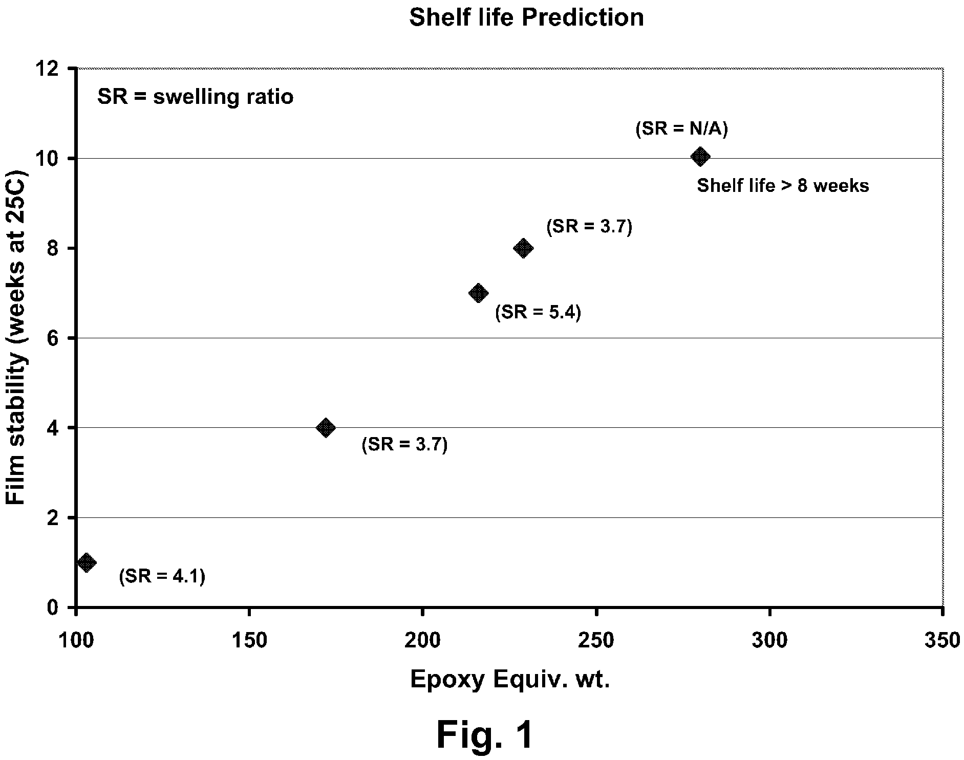
TABLE 3SampleEpoxy85° C. cure (50 hrs, N2)(% x-linker basedequivalent25° C. cureSwelling in Acetoneon solids)wt.(weeks)(Lf / Li)3Diglycidyl1034.1aniline (5%)(6 days)Vikoflex1724-53.77190 (10%)Vikoflex280>8 weeksDe-wetted4050 (10%)Vikoflex2166-75.49080 (10%)Vikoflex2297-83.77170 (10%)

[0107]The data in Table 3 confirm that epoxidized fatty acids and esters give good adhesive film stability and high cross-linking density.

[0108]Further experiments were conducted to confirm that the increase in film stability time at low temperatures experienced with DGA was also found with the epoxidized fatty acid esters. For this purpose, adhesive compositions containing 8.6 and 14.3 percent by weight (on a solids basis) of Vikoflex 7190 were...

example 3

Direct Mechanical Analysis Results

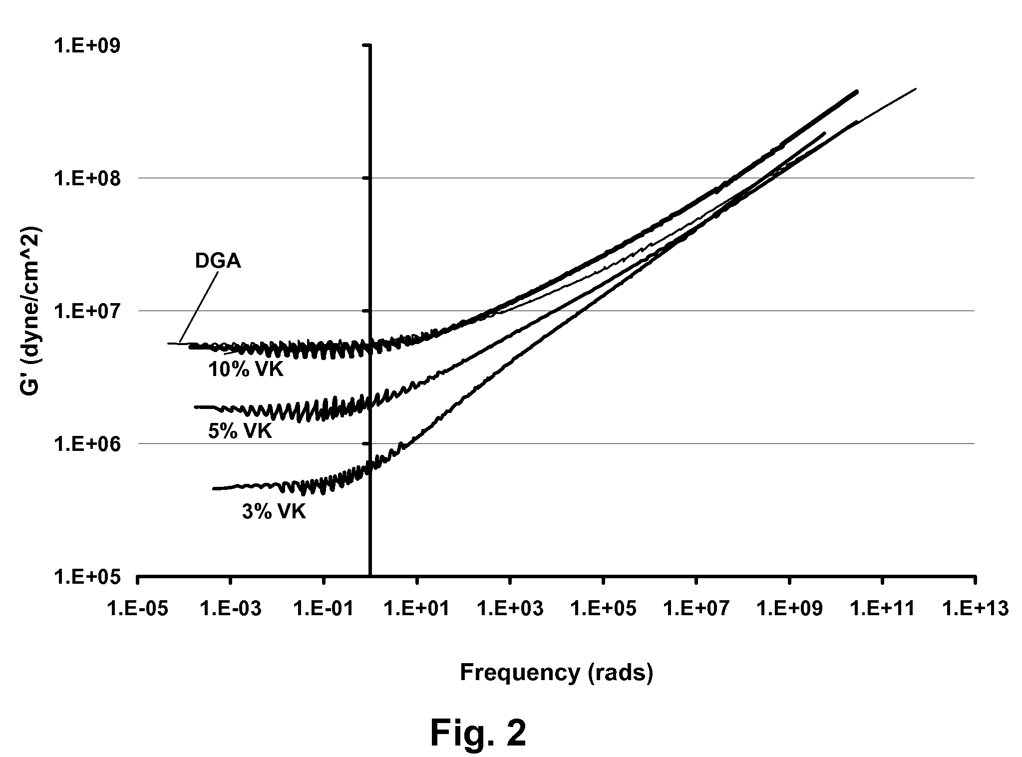
[0110]Adhesive compositions containing the same polyurethane as in the previous Examples and 3, 5 and 10 percent (on a solids basis) of Vikoflex 7190 and 5 percent (on a solids basis) of DGA were prepared. Each composition was coated on to a release sheet and dried at 25° C. for approximately 24 hours, the coating weight of the dispersion being controlled so that an adhesive layer 50 μm thick was formed on the release sheet. The adhesive layer was then cured at 85° C. for 50 hours in a nitrogen-purged oven.

[0111]The cured adhesive layer was peeled from the release sheet and folded into multiple thicknesses to provide an adhesive layer sufficiently thick for shear modulus testing, which was conducted on a Dynamic Mechanical Analyzer, Model RDA III. The results were converted to corresponding values at 70° C., and the results are shown in FIG. 2 of the accompanying drawings. From FIG. 2 it will be seen that (as expected) the shear modulus (stiffness) ...


PUM

PropertyMeasurementUnit
temperaturesaaaaaaaaaa
resistivitiesaaaaaaaaaa
temperatureaaaaaaaaaa

Abstract

An electro-optic display comprises a layer of solid electro-optic material; a backplane comprising at least one electrode; and an adhesive layer disposed between the layer of electro-optic material and the backplane and adhesively securing the layer of electro-optic material to the backplane, the adhesive layer comprising a thermally-activated cross-linking agent comprising an epoxidized vegetable oil fatty acid or an epoxidized ester of such a fatty acid. The cross-linking agent reduces void growth when the display is subjected to temperature changes.

Description

REFERENCE TO RELATED APPLICATIONS[0001]This application is a continuation-in-part of application Ser. No. 11 / 613,259, filed Dec. 20, 2006, which is itself a divisional of application Ser. No. 10 / 904,351, filed Nov. 5, 2004 (now U.S. Pat. No. 7,173,752, issued Feb. 6, 2007), which itself claims benefit of Application Ser. No. 60 / 481,600, filed Nov. 5, 2003, of Application Ser. No. 60 / 481,605, filed Nov. 6, 2003, and of Application Ser. No. 60 / 481,787, filed Dec. 14, 2003.[0002]This application is related to:[0003](a) U.S. Pat. No. 6,831,769;[0004](b) copending application Ser. No. 10 / 898,027, filed Jul. 23, 2004 (Publication No. 2005 / 0122563);[0005](c) U.S. Pat. No. 7,012,735;[0006](d) U.S. Pat. No. 7,110,164.[0007]The entire contents of the aforementioned applications and patents are herein incorporated by reference. The entire contents of all United States patents and published and copending applications mentioned below are also herein incorporated by reference.BACKGROUND OF INVENT...

Claims


Application Information

Patent Timeline
Patent Type & Authority Patents(United States)
IPC IPC(8): G02F1/00B32B15/04B32B7/12G02F1/03G02F1/167G02F1/1675
CPCC08G18/0804C08G18/4825C08G18/765C09J175/08Y10T428/24Y10T428/14Y10T428/2891Y10T428/28Y10T428/1476G02F2202/28G02F1/167G02F1/1675
Inventor FAZEL, SHAFIQ N.DANNER, GUY M.CAO, LANMILLER, DAVID D.KLINGENBERG, ERIC H.
Owner E INK CORPORATION
Why Eureka
Try Eureka