Optical fiber delivery system for delivering ultrashort optical pulses and optical system including the same

a technology of optical fiber and ultrashort pulses, applied in the direction of cladded optical fibre, multiplex communication, instruments, etc., can solve the problems of inability to obtain the desired position, the ultrashort pulses each have high peak power and a desired width, and the problem of pulse broadening is problematic in many applications, so as to achieve efficient transmission of high peak power

Active Publication Date: 2009-06-23
OLYMPUS CORP
View PDF9 Cites 23 Cited by
  • Summary
  • Abstract
  • Description
  • Claims
  • Application Information

AI Technical Summary

Benefits of technology

[0018]Therefore, an object of the present invention, which has been made in view of such circumstances, is to provide an optical fiber delivery system for delivering ultrashort optical pulses that can efficiently transmit high peak power, ultrashort optical pulses from an optical pulse source to a desired position in an optical apparatus, and an optical system including such an optical fiber delivery system.
[0062]According to the present invention, since high-peak power, ultrashort optical pulses are transmitted through the light waveguide means, the negative group-velocity dispersion generation means, and the optical fiber, and the ultrashort optical pulses are converted into down-chirped pulses, the optical pulses can be efficiently transmitted to the optical apparatus that uses the optical pulses in such a way that high-peak power, ultrashort optical pulses are provided at a desired position.

Problems solved by technology

Such pulse broadening is problematic in many applications.
Therefore, when high-peak power, ultrashort optical pulses are incident on the optical system through the optical fiber delivery system described above, the GVD effect of the optics system in the optical apparatus broadens the pulse width in the optics system, and hence ultrashort optical pulses, each having high peak power and a desired width, cannot be obtained at a desired position.

Method used


Image

  • Optical fiber delivery system for delivering ultrashort optical pulses and optical system including the same
  • Optical fiber delivery system for delivering ultrashort optical pulses and optical system including the same
  • Optical fiber delivery system for delivering ultrashort optical pulses and optical system including the same

Examples


first embodiment

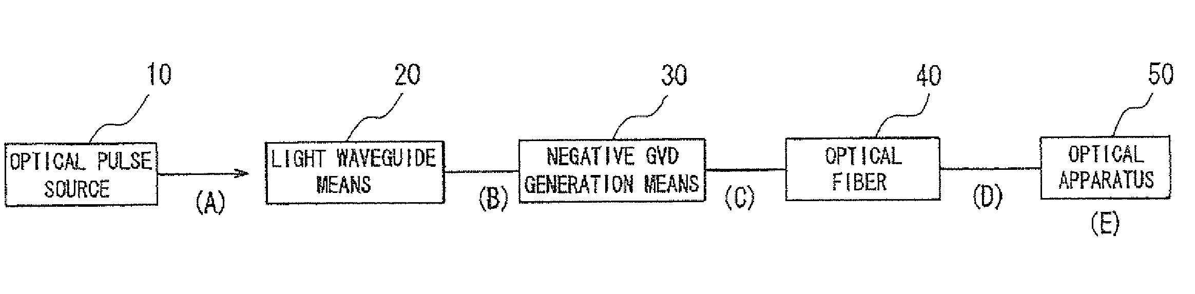
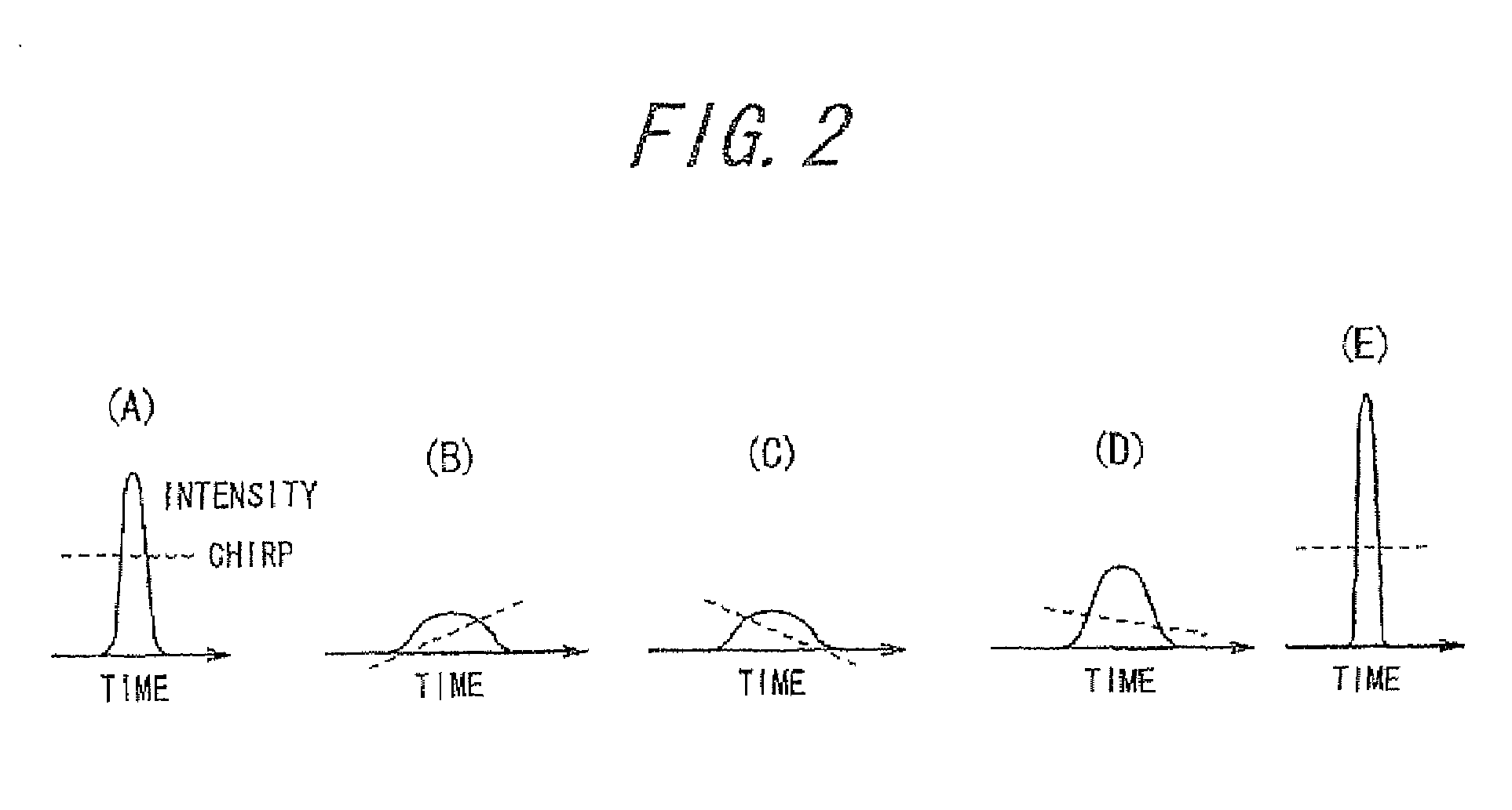
[0074]FIGS. 1 to 3 show a first embodiment of the present invention. FIG. 1 is a block diagram showing a schematic configuration of an optical system including an optical fiber delivery system for delivering ultrashort optical pulses. FIGS. 2(A) to 2(F) and FIGS. 3(A) to 3( ) show temporal profiles and spectral profiles of an optical pulse in the portions (A) to (E) in FIG. 1, respectively. In FIGS. 2(A) to 2(E), the broken lines indicate a chirp.

[0075]The optical system according to the present embodiment includes au optical pulse source 10, light wave guide means 20, negative GVD generation means 30, an optical fiber 40, and an optical apparatus 50 that has a positive GVD value and uses ultrashort optical pulses. The optical pulse source 10 is any one of a titanium: sapphire laser, a mode-locked rare earth doped optical fiber laser, a mode-locked semiconductor laser, and a gain-switched semiconductor laser, or any one of the above lasers combined with an optical amplifier so as to...

second embodiment

[0088]FIG. 5 is a block diagram showing a schematic configuration of an optical system including an optical fiber delivery system for delivering ultrashort optical pulses according to a second embodiment of the present invention. In the present embodiment, positive GVD generation means 60 that provides a positive GVD is added between the optical fiber 40 and the optical apparatus 50 in the configuration shown in FIG. 1 in order to adjust the degree of the down-chirp of the optical pulses to be incident on the optical apparatus 50. In this way, ultrashort optical pulses) having high peak power and a desired width, are provided at a desired position in the optical apparatus 50. The positive GVD generation means 60 is, for example, an ZnSe substrate, which is a light-transmitting substrate, a collimator lens, an acousto-optic (AO) device, or an electrooptic (EO) device.

[0089]FIG. 6 shows an exemplary specific configuration of the optical system according to the second embodiment. In th...

third embodiment

[0093]FIG. 7 is a block diagram showing a schematic configuration of an optical system including an optical fiber delivery system for delivering ultrashort optical pulses according to a third embodiment of the present invention. In the present embodiment, wavelength conversion means 70 is disposed between the optical fiber 40 and the optical apparatus 50 in the configuration shown in FIG. 1, so that the wavelength of the optical pulses is converted into a desired wavelength.

[0094]FIG. 8 shows an exemplary specific configuration of the optical system according to the third embodiment. In the optical system, the optical pulse source 10 is a mode-locked Er-doped fiber laser 13 that produces optical pulses having an operation wavelength of 1550 nm, a pulse width of approximately 500 fs, a repetition rate of 20 MHz, and an average optical output of approximately 10 mW.

[0095]The light waveguide means 20 is an optical fiber amplifier. In the optical fiber amplifier, the optical pulses from...


PUM

PropertyMeasurementUnit
poweraaaaaaaaaa
operation wavelengthaaaaaaaaaa
lengthaaaaaaaaaa

Abstract

An optical fiber delivery system for delivering ultrashort optical pulses that can efficiently transmit high peak power, ultrashort optical pulses from an optical pulse source to a desired position in an optical apparatus is provided. An optical system including such an optical fiber delivery system is also provided. The optical fiber delivery system includes light waveguide means 20 for receiving high-peak power, ultrashort optical pulses and transmitting the optical pulses, negative group-velocity dispersion generation means 30 for providing negative group-velocity dispersion to the optical pulses transmitted through the light waveguide means 20, and an optical fiber 40 that transmits the optical pulses transmitted through the negative group-velocity dispersion generation means 30 along a desired distance. The incident ultrashort optical pulses that have been injected into the light waveguide means 20 are converted into down-chirped pulses.

Description

BACKGROUND OF THE INVENTION[0001]1. Field of the Invention[0002]The present invention relates to an optical fiber delivery system for delivering ultrashort optical pulses and an optical system including the same.[0003]This application claims priority from Japanese Patent Application No. 2007-112042) filed on Apr. 20, 2007, the content of which is incorporated herein by reference.[0004]2. Description of the Related Art[0005]In recent years, sub-picosecond ultrashort optical pulses, having high peak power and broad spectrum, have been used in various fields, such as biology, medicine, medical care, processing, and measurement. In particular, in the fields of biology and medicine, an optical pulse source that generates ultrashort optical pulses, such as a titanium: sapphire laser and a fiber laser, has been frequently used in a microscope using nonlinear optical effects, such as a multi-photon fluorescence microscope, a harmonic generation microscope, and a coherent anti-Stokes Raman s...

Claims


Application Information

Patent Timeline
Patent Type & Authority Patents(United States)
IPC IPC(8): G02F1/01H01S3/00H04J14/02
CPCG02F1/011H04B10/25137G02F2203/255
Inventor TAIRA, KENJIKUBO, HIROKAZU
Owner OLYMPUS CORP
Why Eureka
Try Eureka