Device for determining strains on fiber composite components

a technology for fiber composite components and devices, applied in the direction of mechanical measurement arrangements, instruments, mechanical means, etc., can solve the problems of affecting the mechanical stiffness and strength of components, affecting the performance of components, so as to achieve the effect of small hysteresis effects, low cost and high measurement accuracy

Inactive Publication Date: 2009-06-30
HOTTINGER BALDWIN MESSTECHNIK GMBH
View PDF29 Cites 51 Cited by
  • Summary
  • Abstract
  • Description
  • Claims
  • Application Information

AI Technical Summary

Benefits of technology

[0013]The invention has the advantage, that due to the integration of the strain gages near the neutral fiber of the composite materials, very flat nearly typical commercially available foil measuring grids can be utilized, whereby these foil measuring grids are not also destroyed by the material loads even in connection with high surface tensions of the composite materials. Thereby, cost-advantageous or economical multi-point measurements are also possible on composite materials, which can be utilized both for the analysis of the material components as well as for the load monitoring and for the longterm continuous monitoring of large surface area components preferably of aircraft body components.
[0014]The invention simultaneously has the advantage, that due to the integration of the strain gages, these can immediately be utilized in the workshop in the production of the composite material components. Thereby, the pick-up or sensor elements are also simultaneously protected against external damages during the component assembly or installation, maintenance, and in operation. Due to the flat foil measuring grids of the strain sensors, these can be inserted in a space-saving manner between the individual composite layers, whereby advantageously the matrix structure of the components is basically not weakened, and additionally a force-transmitting connection between the sensor elements and the strain-relevant composite materials is achievable. Since such a connection is also achieved on both sides, only small hysteresis effects arise in the measuring operation, so that high measuring accuracies can be achieved.
[0015]The sensor elements according to the invention have the advantage, that nearly all loading types on fiber composite materials are detectable in a cost-advantageous or economical manner during the operating time using typical commercially available foil measuring grids. An advantageous integration possibility is simultaneously achieved through the provided connecting pins, through which a subsequent wiring-connection via plug connections is made possible. The embodiment according to the invention with the provided connecting pins especially allows a high degree of automation in the integrated composite material production, because connection wires that are to be lead out do not need to be taken into account in the production technique, and nonetheless a subsequent quick connection possibility is provided.

Problems solved by technology

Moreover, damages such as cracks or delaminations can arise in the material of lightweight structures due to high loads or through too-high production tolerances, such as shrinkage voids or sink holes or fiber proportions or components.
These damages can considerably weaken the mechanical stiffness and the strength of the components.
Especially in connection with aircraft, such components are also subjected to the danger of impact damages through birds and ice particles during operation.
These loads can lead to previously mentioned damages within the composite materials, which are not externally visible and represent an endangerment of safety.
However, in that regard the danger exists, that a clear reduction of the operating strength arises until the time of the next maintenance inspection due to damage growth as a result of high vibration or oscillation loads, whereby such reduction of the operating strength is to be avoided in all cases.
However, with such a monitoring apparatus, only excessive impact loadings that can lead to a delamination are detectable.
Such a monitoring of the material surfaces is, however, only possible where this surface can be radiated with laser light and the reflected or re-radiation intensity thereof is detectable at a certain spacing distance from the surface.
Especially when the surfaces are additionally provided with other protective or insulation layers, which do not follow the strain, then such a monitoring or a strain examination cannot be carried out.
For that purpose, apparently commercially available typical strain gages are used, which are not suitable for measurements of strain tending toward damage on fiber composite material surfaces, because typical commercially available measuring grids do not withstand such strain regions.
Therefore, such typical commercially available strain gages would have to be renewed after each examination test run or each loading with surface strains tending to cause damage, which brings about a considerable cost-intensive expense and effort especially in connection with multi-point measurements.
Especially, in material analysis measurements, no measured values could further be evaluated in the upper damage-inducing range, so that thereby also only an inadequate analysis result can be achieved.
While it is conceivable to produce special strain gages of wire measuring grids for such surface tension measurements, which wire measuring grids also withstand greater strain ranges on composite fiber surfaces, which would be uneconomical, however, for multi-point measurements for component analysis or for the monitoring of large surface area aircraft parts.
Such a strain gage can basically be applied only on the surface of a strain body, because otherwise a subsequent wiring-connection is no longer possible.
A previous wiring-connection would also be unrealistic, because an economical handling of a plurality of connection wires is hardly possible in the known production methods of composite materials.

Method used


Image

  • Device for determining strains on fiber composite components
  • Device for determining strains on fiber composite components
  • Device for determining strains on fiber composite components

Examples


Embodiment Construction

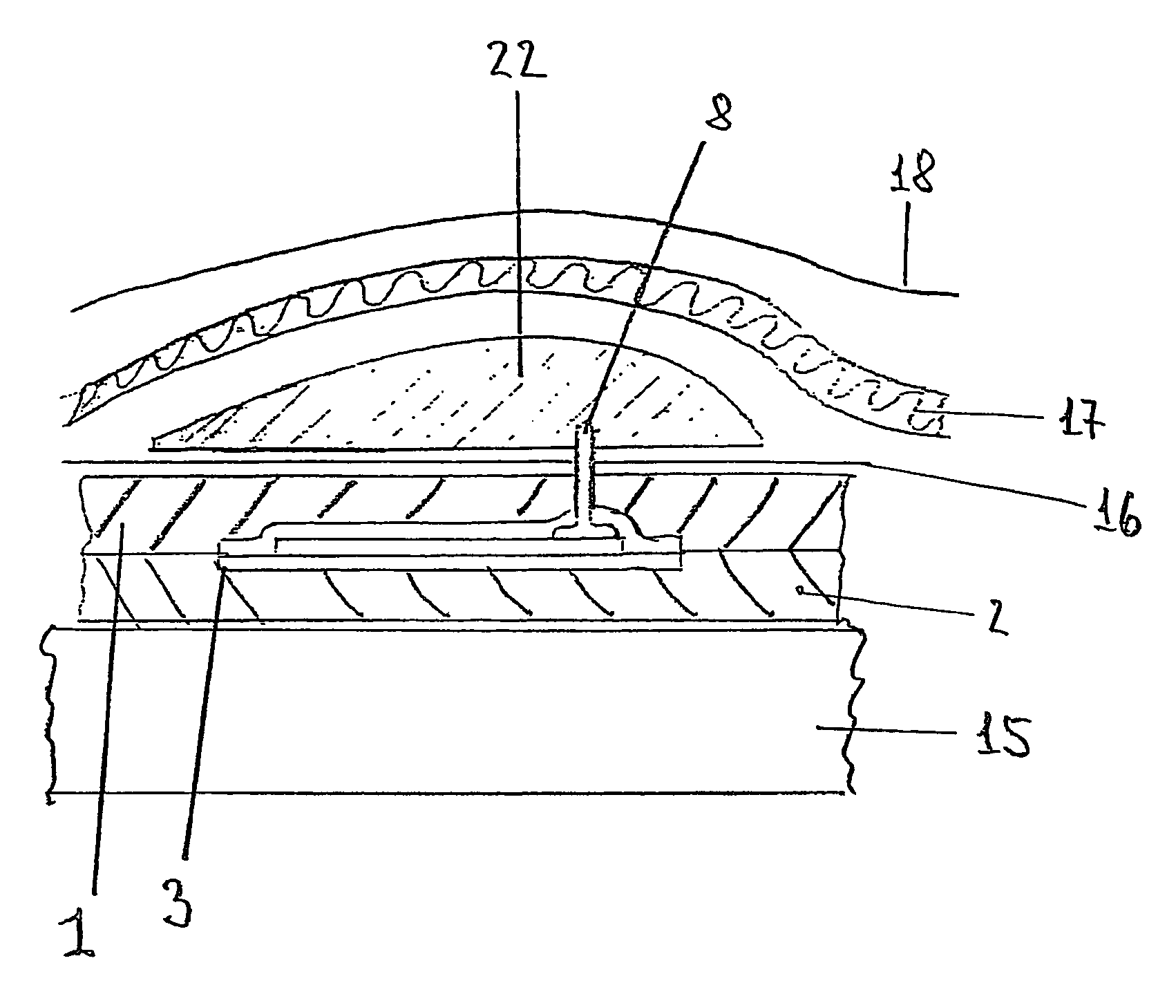
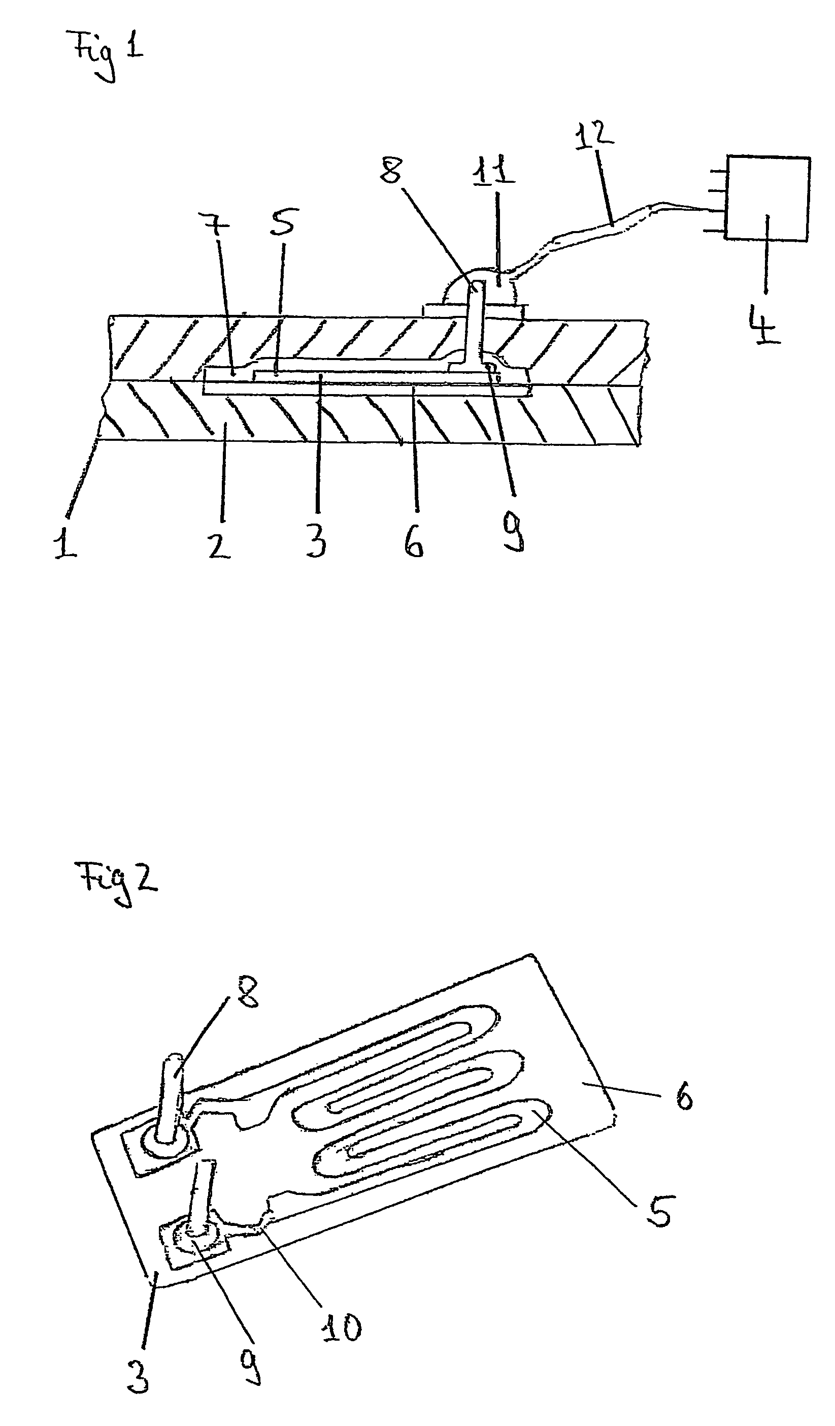
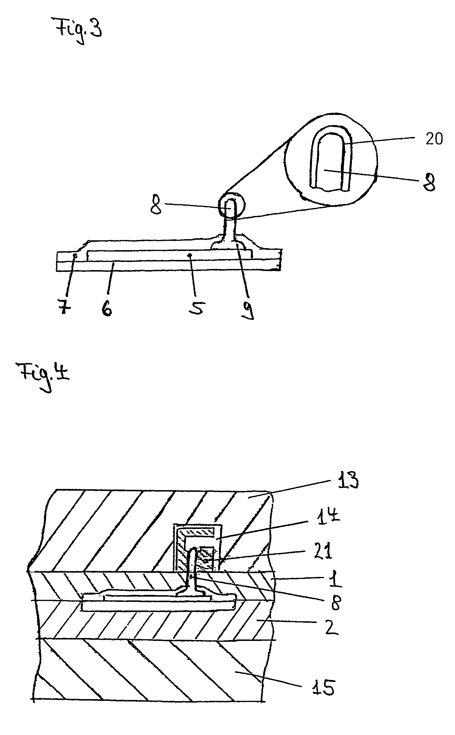
[0023]FIG. 1 of the drawing shows, in a partial cut-out section manner, an apparatus for the determination of a strain or for the inspection and for the load monitoring on a fiber composite material component 1 with a foil strain gage 3 integrated in the fiber layers 2 and with a connected evaluating apparatus 4.

[0024]The fiber composite material component 1 is illustrated only in a partial cut-out portion, of a fiber composite material consisting of only two layers 2, between which the strain gage 3 is arranged. Such fiber composite materials 1 generally consist of plural layers, preferably of glass, carbon or aramid fiber plies. These are usually laid one on top of another and are impregnated by means of a polymeric material, and are thereby fixedly or rigidly connected with one another. Depending on the desired strength requirements, fiber layers are laid one on top of another and are oriented in the force and tension direction.

[0025]Such fiber composite material components are u...


PUM

PropertyMeasurementUnit
diameteraaaaaaaaaa
lengthaaaaaaaaaa
thicknessesaaaaaaaaaa

Abstract

In an apparatus for determining loads on fiber composite components (1), especially of vehicle and aircraft parts, strain gages (3) are integrated in the components (1) for determining strains. The strain gages (3) are connected with an evaluating apparatus (4), for monitoring and determining loads that tend to cause damage. The strain gages (3) are preferably integrated into the fiber composite component (1) such that the measuring grids (5) thereof are laid between individual fiber layers (2) and are guided out of the component (1) ready for connection via special connecting pins (8) to the associated evaluating apparatus (4) via loose cable connections (12).

Description

FIELD OF THE INVENTION[0001]The invention relates to an apparatus for the determination of loads on fiber composite components as well as production methods thereof and a pick-up or sensor element for the apparatus.BACKGROUND INFORMATION[0002]Ever more components of fiber composite materials are used in the construction of vehicles and aircraft. These fiber composite materials preferably consist of glass, carbon or aramid fibers, which are built-up of fiber layers and connected with one another through polymer materials. In that regard, the components are generally produced through lamination of the synthetic resin impregnated fiber layers under pressure and heat in a pressing form or mold. These composite materials are usually lighter than comparable metal structural parts and possess a high stiffness and strength and are therefore preferably utilized in aircraft construction.[0003]For such structures, the exact documentation of the operational loads is of great interest, in order ...

Claims


Application Information

Patent Timeline
Patent Type & Authority Patents(United States)
IPC IPC(8): G01B7/16G01L1/22G01M5/00G01N3/00G01N3/06G01N3/08
CPCG01L1/2287G01M5/0033G01M5/0041G01N3/08G01N2203/0017G01N2203/0062G01N2203/0073G01N2203/0075G01N2203/0623
Inventor HAASE, KARL-HEINZHECKER, CARSTENKLEIN, SEBASTIANGLASER, SIGMUND
Owner HOTTINGER BALDWIN MESSTECHNIK GMBH
Why Eureka
Try Eureka