System and method for providing a configurable inductor less multi-stage low-noise amplifier

a multi-stage, low-noise technology, applied in the field of processing, to achieve the effect of reducing or eliminating at least some disadvantages

Active Publication Date: 2009-09-29
FUJITSU LTD
View PDF2 Cites 14 Cited by
  • Summary
  • Abstract
  • Description
  • Claims
  • Application Information

AI Technical Summary

Benefits of technology

[0004]The present invention provides a method and a system for providing a configurable inductor less multi-stage low-noise amplifier that substantially eliminates or reduces at least some of the disadvantages and problems associated with previous methods and systems.
[0006]In more specific embodiments, the LNA is used to provide a wide frequency band and a defined input impedance. In other embodiments, the LNA achieves a low noise parameter and low output distortion. In addition, the LNA can use a ladder network of grounded switches and floating resistors in order to avoid floating switches in a feedback path. The LNA can increase parametric yield. The LNA can be used to control noise, gain, distortion, and input impedance independently. Moreover, the LNA can be used in software defined radio systems. Specifically, the LNA can be used in a system where noise, linearity, gain, or input matching is targeted.

Problems solved by technology

Therefore, the ability to properly resolve these significant processing issues in the field of electronics creates an interesting challenge.
As with all such processing operations, of critical importance are issues relating to speed, quality, minimal board space consumption, accuracy, and automation.

Method used


Image

  • System and method for providing a configurable inductor less multi-stage low-noise amplifier
  • System and method for providing a configurable inductor less multi-stage low-noise amplifier
  • System and method for providing a configurable inductor less multi-stage low-noise amplifier

Examples


Embodiment Construction

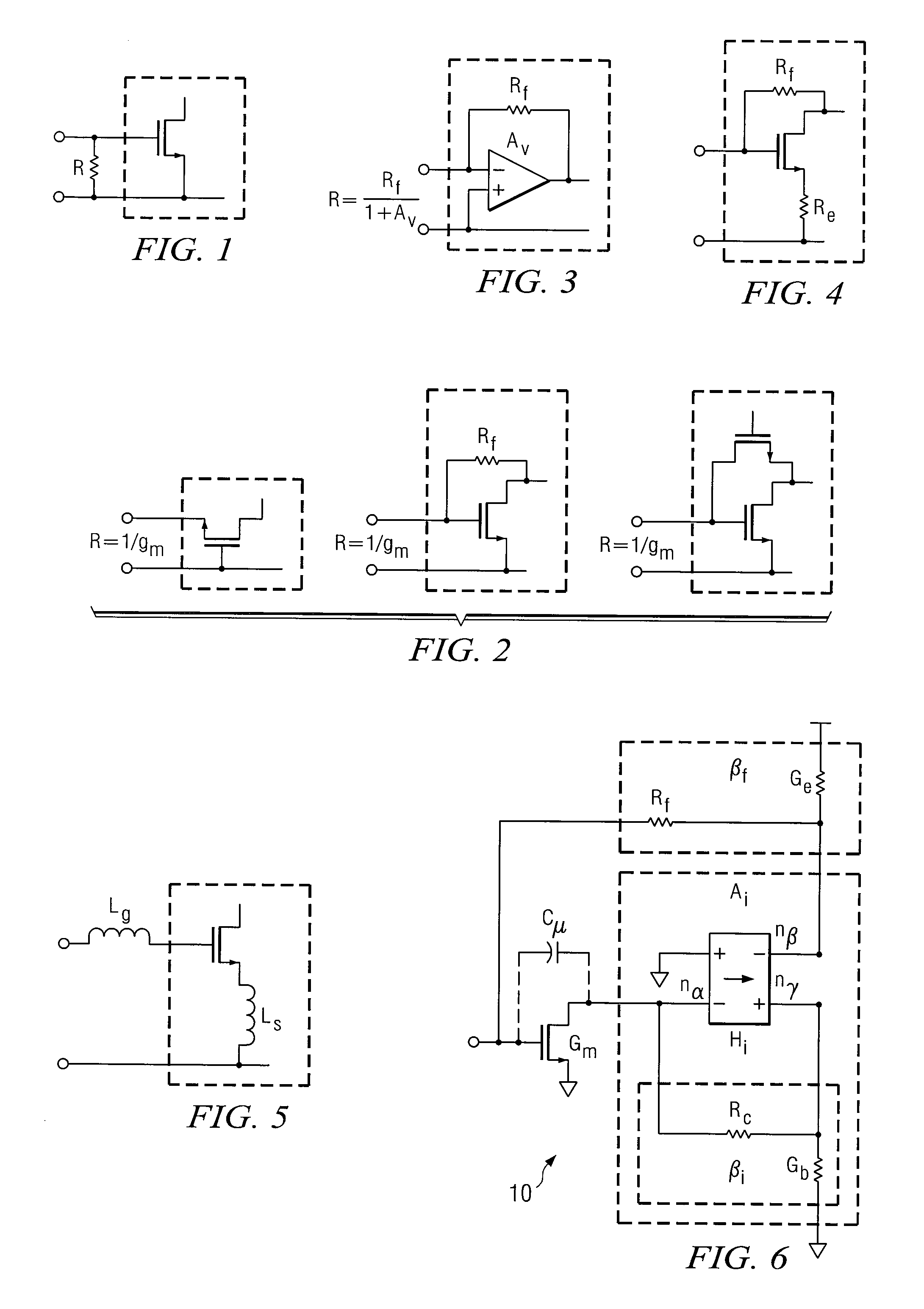
[0022]FIG. 1 is a simplified block diagram illustrating an example system that includes an input matching resistor. Note that several techniques to achieve input matching are currently in existence. FIG. 1 depicts a simple input resistor that defines the input matching.

[0023]FIG. 2 is a simplified block diagram illustrating a common gate amplifier and other current feedback one-stage amplifiers. This depiction shows the common gate amplifier, where input impedance is determined by the inverse of the transconductance: Rin=1 / gm. FIG. 3 is a simplified diagram illustrating a transimpedance amplifier. The depicted transimpedance feedback amplifier offers an amplifier, two-stages, that has a voltage gain of Av. With a shunt feedback resistor Rf, the input impedance is given by Rin=Rf / (1+Av).

[0024]FIG. 4 is a simplified block diagram illustrating a series-shunt amplifier. This particular shunt-series amplifier includes two feedback loops: one shunt feedback resistor and one series feedbac...


PUM


Abstract

In accordance with a particular embodiment of the present invention, an apparatus is offered that includes a configurable feedback low noise amplifier (LNA) connected to a common source connected input transistor to realize a specific value of an input impedance, the input impedance being controlled by transconductance, the overall gain being defined by a global current feedback network. In more specific embodiments, the LNA is used to provide a wide frequency band and a defined input impedance. In other embodiments, the LNA achieves a low noise parameter and low output distortion. Also, the LNA can use a ladder network of grounded switches and floating resistors in order to avoid floating switches in a feedback path. The LNA can increase parametric yield. The LNA can be used to control noise, gain, distortion, and input impedance independently.

Description

TECHNICAL FIELD OF THE INVENTION[0001]This invention relates generally to the field of processing and, more specifically, to a configurable inductor less multi-stage low-noise amplifier.BACKGROUND OF THE INVENTION[0002]Inductors are ubiquitous in today's processing world and may be especially prevalent in radio systems (e.g. in a given headset). A low noise amplifier (LNA) is typically used as the first stage at the antenna (sometimes there is a filter between the antenna and the LNA) and with a purpose to amplify the received weak RF signals from an antenna. For ideal reception, the LNA should be power matched to the source that is driving the input of the antenna. A good match usually means to provide 50 hm input impedance. In case there is a filter and a balun between the antenna and the LNA, the optimal input matching impedance may be different.[0003]The LNA should also provide enough gain such that the amplified signal could be further processed with enough signal-to-noise rati...

Claims


Application Information

Patent Timeline
Patent Type & Authority Patents(United States)
IPC IPC(8): H03G3/30
CPCH03F1/26H03F1/301H03F1/3205H03F1/342H03F3/195H03G1/0088H03G1/0035H03F2200/222H03F2200/294H03F2200/411H03F2200/453H03F2200/129
Inventor WIKLUND, MAGNUS O.
Owner FUJITSU LTD
Why Eureka
Try Eureka