High efficiency incandescent bulb replacement lamp

a replacement lamp and high efficiency technology, applied in the direction of semiconductor devices for light sources, lighting and heating apparatus, lighting support devices, etc., can solve the problems of light bulbs, light bulbs, and light sources that are very energy inefficient, and achieve high efficiency, high power factor, and high efficiency.

Inactive Publication Date: 2009-10-13
LEDNOVATION
View PDF19 Cites 146 Cited by
  • Summary
  • Abstract
  • Description
  • Claims
  • Application Information

AI Technical Summary

Benefits of technology

[0022]In an additional embodiment according to the present invention, the high efficiency electrical AC / DC conversion member converts at least 90% of AC power from an Edison mount socket into a DC driving current to inject high efficiency DC current into the LED board with a high power factor. A single chip based controller in a close loop Pulse Width Current Modulator drives a single high side Field Effect Transistor (FET). The FET is driven with an internal ramp compensation and built in frequency jittering for low electromagnetic interference. With the controller internal operating frequency set, the device supplies itself from the high voltage rail with the voltage required to drive the FET and in doing so avoids a transformer auxiliary winding. This design feature allows a driver without a bulky transformer which is a very desirable condition in the system of the present invention due to major space constraints. The current mode control also provides excellent pulse by pulse current control which allows for good load response variations. Additionally, the internal ramp compensation prevents sub-harmonic oscillations from taking place in continuous conduction mode operation. When the current set point falls below a given value, the output power demand diminishes; then the controller enters a skip cycle mode and provides excellent efficiency at light loads. This would be a requirement when dimming occurs at the bulb lever by the user. The driver design also provides efficient protective circuitry for over voltage and current conditions.

Problems solved by technology

It is well known that incandescent light bulbs are a very energy inefficient light source—about 90% of the electricity they consume is released as heat rather than light.
Fluorescent light bulbs are by a factor of about 10 more efficient, but are still less efficient than a solid state semiconductor emitter, such as light emitting diodes, by a factor of about 2.
In addition, incandescent light bulbs have a relatively short lifetime, i.e., typically about 750-1000 hours.
Fluorescent bulbs have a longer lifetime (e.g., 10,000 to 20,000 hours) than incandescent lights, but they contain mercury, not an environment friendly light source, and they provide a less favorable color reproduction.
This type of white solid state light device is not desirable for some applications, like indoor applications, which require a warm white color temperature of about 2700 K to 3500 K with a high color rending index Ra above 80.
However, there are low luminous efficacy issues caused by: a) multi-phosphors self-absorption loss of the photons excited from the green and orange phosphor particles; and b) Stoked-shift loss from blue-to-red wavelength conversion.

Method used


Image

  • High efficiency incandescent bulb replacement lamp
  • High efficiency incandescent bulb replacement lamp
  • High efficiency incandescent bulb replacement lamp

Examples


Embodiment Construction

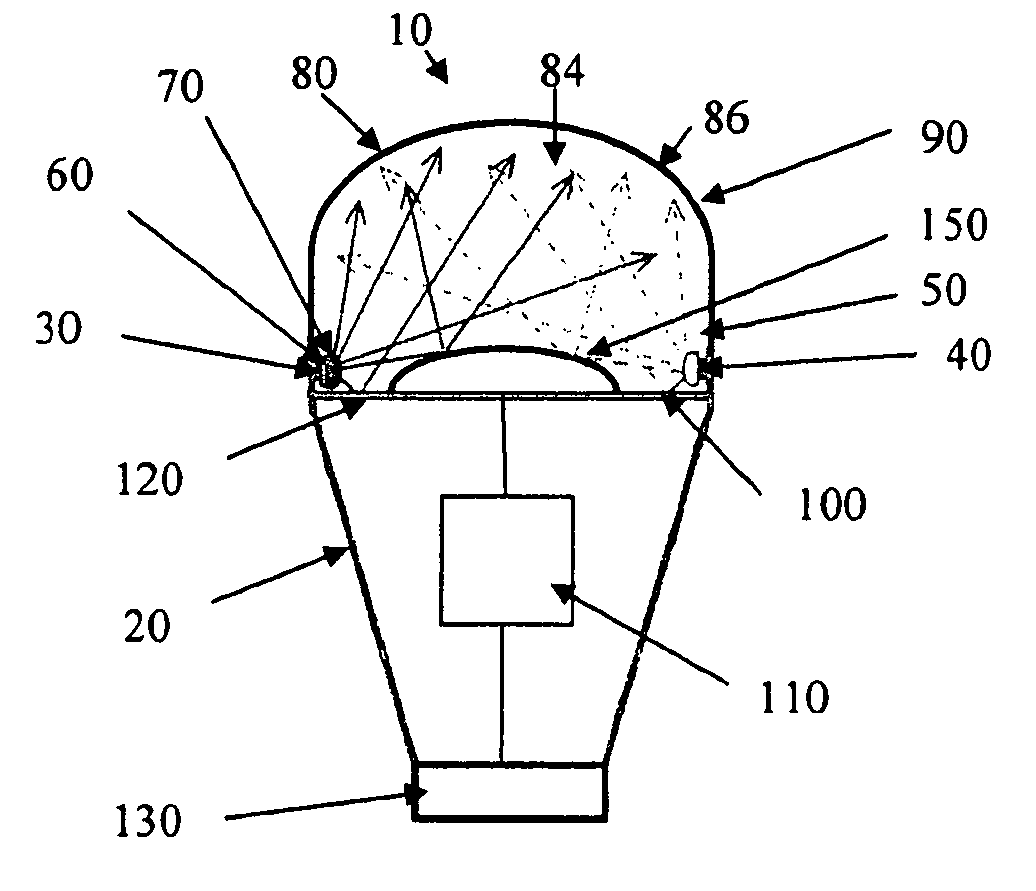
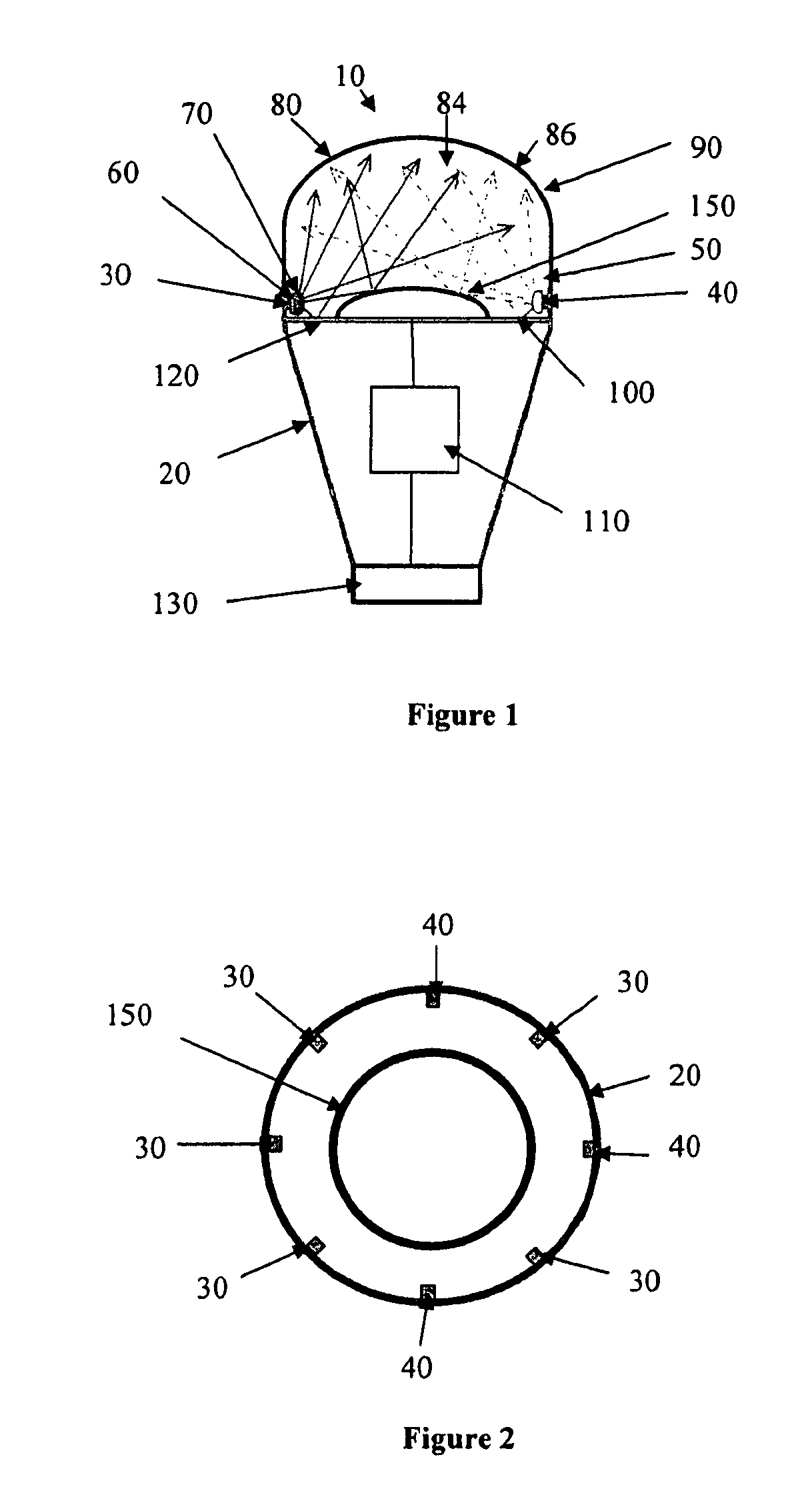
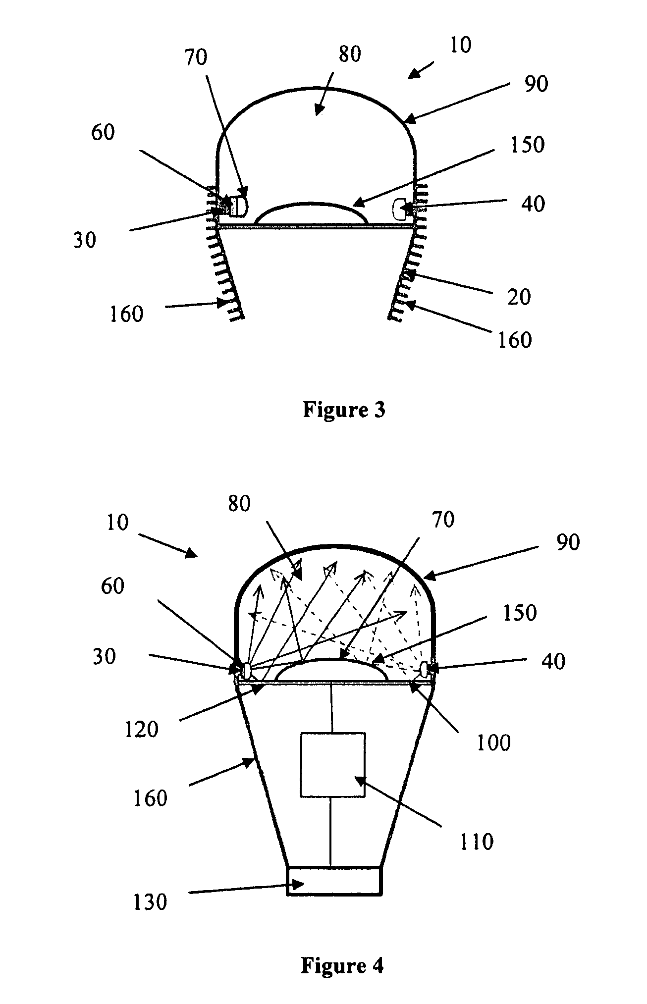
[0030]As shown in FIG. 1, an LED-based light bulb 10 of the present invention comprising a plurality of semiconductor light devices that can be mounted radially around the interior annular side wall 50 of the light bulb's thermal conductive body 20 inside a light mixing cavity 80. The plurality of semiconductor light devices includes two groups of semiconductor light emitters that emit four different hues of light and a first luminescent material 60. The first group of semiconductor light emitters 30 produce a mixture of white light from an emitted primary hue of light and an excited second long wavelength hue of light. The second group of semiconductor light emitters 40 produce an emitted fourth hue of light in the red spectrum range.

[0031]In one embodiment, each light emitter of the first group of semiconductor light emitters 30 and the second group of semiconductor light emitters 40 can be circumferentially spaced apart from one another about a periphery of the interior annular s...


PUM


Abstract

The invention discloses a high efficiency incandescent and Compact Fluorescent (CFL) bulb replacement LED lamp having a good color reproduction. The LED light bulb includes two groups of semiconductor light emitters and a luminescent material to emit four different spectrums of light. The two groups of semiconductor light emitters are enclosed around an interior wall of the light bulb housing, which has a plurality of fins at an exterior surface for effective heat dissipation. A high reflective member having a dome shape in the center is disposed under the two groups of semiconductor light emitters to redirect the emission and excitation lights from the two groups of semiconductor light emitters and recycle the backscattered light for multi-spectrum light mixing. The LED-light bulb further includes a single power line connecting to the two groups of semiconductor light emitters and a high efficiency electrical AC/DC conversion and control device. The light bulb has a diffuser dome for an output window and a conventional Edison-mount screw-type light bulb socket, a conventional fluorescent tube coupler arrangement or a conventional halogen MR-16 socket arrangement connecting to an AC power base. If a voltage is supplied to the AC/DC conversion and control device, a mixture light from the diffuser dome produces a warm white light with a color rendering index of at least 85 and a luminous efficacy of at least 80 lumens per watt.

Description

FIELD OF INVENTION[0001]The invention relates generally to an incandescent bulb replacement lamp, as well as related components, systems and methods, and more particularly to methods to make a warm white light bulb with a high color rendering and a high luminous efficacy.BACKGROUND OF THE INVENTION[0002]It is well known that incandescent light bulbs are a very energy inefficient light source—about 90% of the electricity they consume is released as heat rather than light. Fluorescent light bulbs are by a factor of about 10 more efficient, but are still less efficient than a solid state semiconductor emitter, such as light emitting diodes, by a factor of about 2.[0003]In addition, incandescent light bulbs have a relatively short lifetime, i.e., typically about 750-1000 hours. Fluorescent bulbs have a longer lifetime (e.g., 10,000 to 20,000 hours) than incandescent lights, but they contain mercury, not an environment friendly light source, and they provide a less favorable color reprod...

Claims


Application Information

Patent Timeline
Patent Type & Authority Patents(United States)
IPC IPC(8): F21V9/16
CPCF21K9/135F21V3/00F21K9/56F21V9/16F21Y2101/02F21V3/02F21K9/50F21Y2103/022F21K9/232F21K9/60F21K9/62F21K9/64F21Y2103/33F21Y2115/10F21V13/08F21V9/32F21V9/38
Inventor MOREJON, ISRAEL J.ZHAI, JINHUIBUI, THONG
Owner LEDNOVATION
Why Eureka
Try Eureka