Magnetic anomaly sensing system for detection, localization and classification of a magnetic object in a cluttered field of magnetic anomalies

Inactive Publication Date: 2009-10-13
USA REPRESENTED BY THE SEC OF THE NAVY
View PDF10 Cites 29 Cited by
  • Summary
  • Abstract
  • Description
  • Claims
  • Application Information

AI Technical Summary

Benefits of technology

[0019]Accordingly, it is an object of the present invention to provide an improved magnetic anomaly se

Problems solved by technology

However, limitations of conventional approaches have limited the development of magnetic gradiometry to experimental devices that do not appear to be practical for general DLC applications.
The limitations of prior art conventional tensor gradiometers include the following:Localization methods that are rather complex, computationally intensive and difficult to implement in a cost effective and easily deployable system.Requirements for sensor platform motion to be impractically constrained to be along nearly constant velocity straight-line paths with very little change in sensor platform orientation.A DLC response that may be too slow for cases where there is fast relative motion between sensor system and target.Accuracy that may be reduced if the target's magnetic signature changes with the target's motion.Data sets that do not allow development of an optimal target discrimination capability for cases where the magnetic signature of a target of interest is convolved with non-target-related magnetic anomalies such as magnetic clutter and/or geo

Method used


Image

  • Magnetic anomaly sensing system for detection, localization and classification of a magnetic object in a cluttered field of magnetic anomalies
  • Magnetic anomaly sensing system for detection, localization and classification of a magnetic object in a cluttered field of magnetic anomalies
  • Magnetic anomaly sensing system for detection, localization and classification of a magnetic object in a cluttered field of magnetic anomalies

Examples


Embodiment Construction

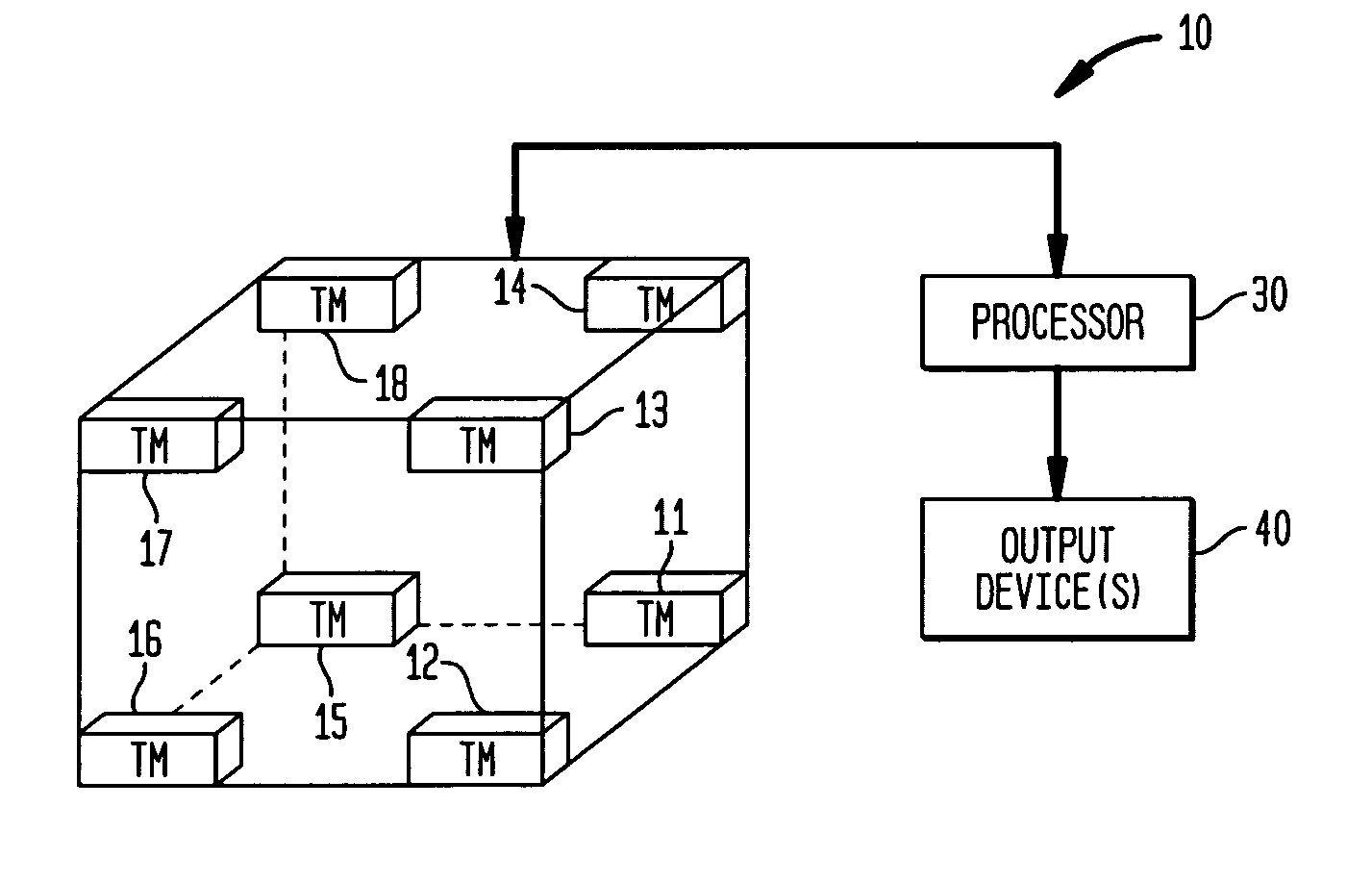
[0041]In general, the present invention is a magnetic anomaly sensing-based system and method for the “detection, localization and classification” (DLC) of stationary and / or moving objects (i.e., “targets”) that have magnetic signatures. The term “target” as used herein refers to any natural or man-made object residing on / under the ground or in the water, with the object having an inherent magnetic signature owing to the ferrous material(s) that are included in the object's physical structure.

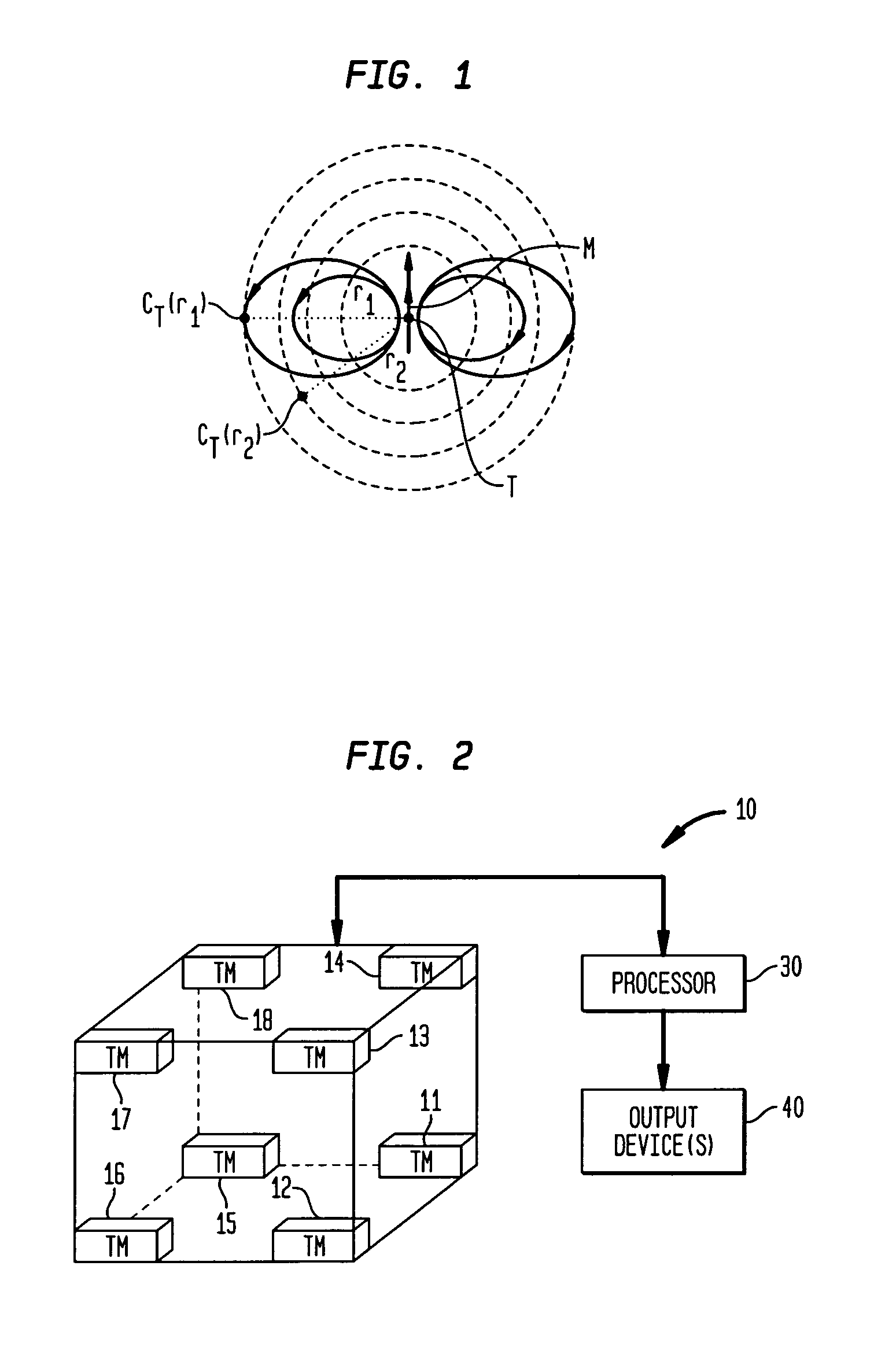
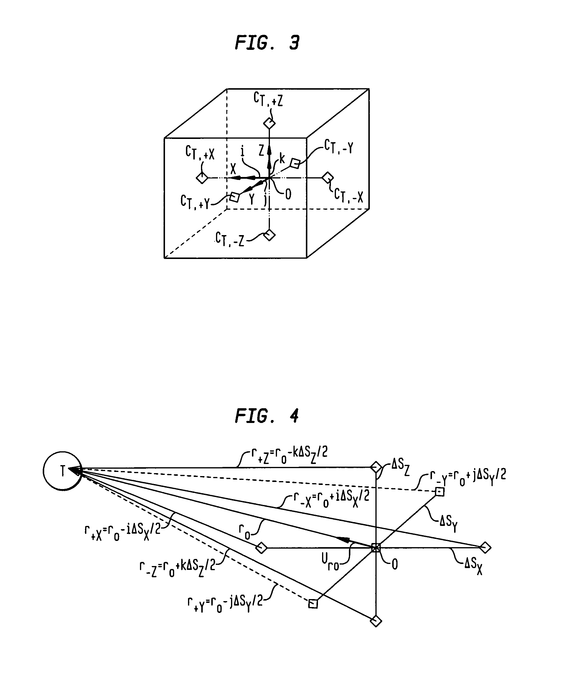
[0042]The present invention's new and improved methods of target localization and discrimination exploit the fact that the gradient contraction CT “field” of a magnetic object is mathematically analogous to a central potential field that emanates from the object. The system includes magnetic sensors and a processor that continually determines magnetic gradient tensors associated with the target and converts the magnetic gradient tensors to gradient contraction scalars. The gradient contraction ...


PUM


Abstract

A magnetic anomaly sensing system and method uses at least eight triaxial magnetometer (TM) sensors arranged to define a cubic space. Each TM sensor measures a local magnetic field associated with a target region and generates magnetic field data indicative thereof. The magnetic field data is processed in accordance with a magnetic scalar triangulation and ranging (STAR) processing scheme to determine a plurality of gradient contractions CT,I at a corresponding plurality of measurement points I to include at least at the center of each face of the cubic space. Gradient contraction pairs are defined for each sensors' X, Y, Z magnetic sensing axes. A directional derivative ∇CT is determined using the gradient contraction pairs and the baseline distances therebetween. A unit vector, calculated using the directional derivative ∇CT, is used in determining a projection distance from each of the measurement points toward the target region.

Description

ORIGIN OF THE INVENTION[0001]The invention described herein was made in the performance of official duties by employees of the Department of the Navy and may be manufactured, used, licensed by or for the Government for any governmental purpose without payment of any royalties thereon.FIELD OF THE INVENTION[0002]The invention relates generally to magnetic sensing systems and more particularly to a magnetic anomaly sensing system that can perform detection, localization and classification of a magnetic object when the object is in a cluttered field of magnetic anomalies.BACKGROUND OF THE INVENTION[0003]There are many potential military and commercial applications for an improved magnetic sensing system that can more effectively and rapidly detect the presence of a magnetic object, locate its position in space, and classify the object in terms of the magnitude and direction of the source of its “magnetic anomaly field”. In particular, there is a need for improved passive magnetic sensi...

Claims


Application Information

Patent Timeline
IPC IPC(8): G01V3/00G06F19/00
CPCG01V3/081G01R33/022
Inventor WIEGERT, ROYOESCHGER, JOHN
Owner USA REPRESENTED BY THE SEC OF THE NAVY
Why Eureka
Try Eureka