Heat exchanger tube

a technology of heat exchanger and heat exchanger tube, which is applied in the direction of light and heating apparatus, machines/engines, laminated elements, etc., can solve the problems of affecting the cooling performance the absolute quantity of flowing fluid is limited naturally, and the durability of the egr valve is deteriorated, so as to prevent accumulation of soot and dirt, reduce the effect of egr valve wear and tear

Inactive Publication Date: 2009-11-10
USUI KOKUSAI SANGYO KAISHA LTD
View PDF16 Cites 22 Cited by
  • Summary
  • Abstract
  • Description
  • Claims
  • Application Information

AI Technical Summary

Benefits of technology

[0010]The present invention has been made to solve the above-described problems, and accordingly an object thereof is to provide a heat exchanger tube used in an EGR gas cooling system which makes it possible to introduce high-temperature EGR gas into the heat exchanger tube (heating tube) incorporated in the EGR gas cooling system with predetermined flow velocity and flow rate although the construction is simple by making improvement on the shape of wave of a corrugated fin structure forming an EGR gas flow path in the flat heating tube for heat exchanger, restrains the accumulation of soot generated in the heating tube and the adhesion of dirt, and is capable of obtaining high heat exchange performance.
[0019]For the heat exchanger tube in accordance with the present invention, the heating tube forming the exhaust gas flow path has a flat cross-sectional shape, and at the same time, the fin structure incorporated on the inner peripheral surface of the flat heating tube is a corrugated fin structure which has a waveform having a substantially rectangular channel-shaped cross section and has the curved surface formed with waveform meandering with a predetermined wavelength in the lengthwise direction. When the wave width of the channel-shaped waveform is let be H, and the wavelength of waveform meandering in the lengthwise direction is let be L, the value indicated by H / L is adjusted so as to be within a range of 0.17 to 0.20, and the value indicated by G / H, where G is a gap determined by a difference (H-A) between the wave width H and the amplitude A of waveform meandering in the lengthwise direction, is adjusted so as to be within a range of −0.21 to 0.19 as basic requirements. Further, at the vertex of waveform meandering in the corrugated fin structure, the radius of curvature R is formed in the range of 1.7 H to 2 H for the wave width H. Thereby, it is found that the exhaust gas flowing in the heating tube while maintaining a specific flow velocity is a region in which the pressure loss is not necessarily at the maximum when the heat exchange performance (heat transfer factor) is at the maximum. In addition, by providing the radius of curvature R in the specific range at the vertex of the waveform, the separation of flow at the vertex of the waveform is restrained, and the accumulation of soot and the adhesion of dirt are prevented. Thus, the heat exchanger tube in accordance with the present invention is formed by determining design values so that the heating tube has a flat cross-sectional shape, and the waveform of transverse cross section of the corrugated fin structure incorporated on the inner peripheral surface of the heating tube and the shape of waveform meandering zigzagging in the lengthwise direction are within predetermined ranges in advance. Thereby, a heat exchanger having effective cooling performance with excellent heat transfer performance can be provided. In order to further increase the effect of the present invention, the Reynolds number is preferably made a value near 2000 by adjusting the number of heating tubes provided in the heat exchanger, and it is preferable to use the heating tube in the region in which the Reynolds number is 5000 or smaller at the most.
[0020]Also, as is apparent from another embodiment in accordance with the present invention, the above-described heating tube can be selected appropriately from the publicly known conventional means. Although the heating tube can be manufactured easily by a very simple fabrication method and the means for joining the corrugated fin structure to the inner peripheral surface of the heating tube is also easy, the obtained effect is remarkably excellent. Therefore, the shell-and-tube type heat exchanger fitted with this heating tube can realize an EGR gas cooling system that is small in size and light in weight at a low cost, so that the present invention can be expected to make great contribution in terms of energy saving.

Problems solved by technology

If the temperature of EGR gas increases, and the quantity of EGR increases, however, the durability of EGR valve is deteriorated by the heat action of EGR gas, and the EGR valve may be broken at an early stage.
However, because of its compact construction, the absolute quantity of flowing fluid has a limit naturally.
As a result, unsolved problems are remained in terms of the total heat exchange efficiency.
In order to solve such problems, what is called a heat exchanger of a shell-and-tube type must inevitably adopted although the construction is somewhat complicated and large.
However, because of its compact construction, the absolute quantity of flowing fluid has a limit naturally.
As a result, unsolved problems are remained in terms of the total heat exchange efficiency.
Actually, however, concerning the shape of wave as the corrugated fin structure that is incorporated in the flat heating tube and can effectively promote heat exchange between the high-temperature fluid flowing in the tube and the cooling medium flowing on the outside of the tube, the optimization has not yet been achieved.
Therefore, substantially, a sufficient performance cannot be obtained, and room for further improvement is left.
In this case, however, the pressure loss increases inversely, and in addition, the adhesion of soot and dirt to the interior of flow path deteriorates the performance because an attempt is made to enhance the heat transfer performance by increasing the flow velocity.
Therefore, there arise new problems of, for example, a serious hindrance in terms of layout.

Method used


Image

  • Heat exchanger tube
  • Heat exchanger tube
  • Heat exchanger tube

Examples


example 1

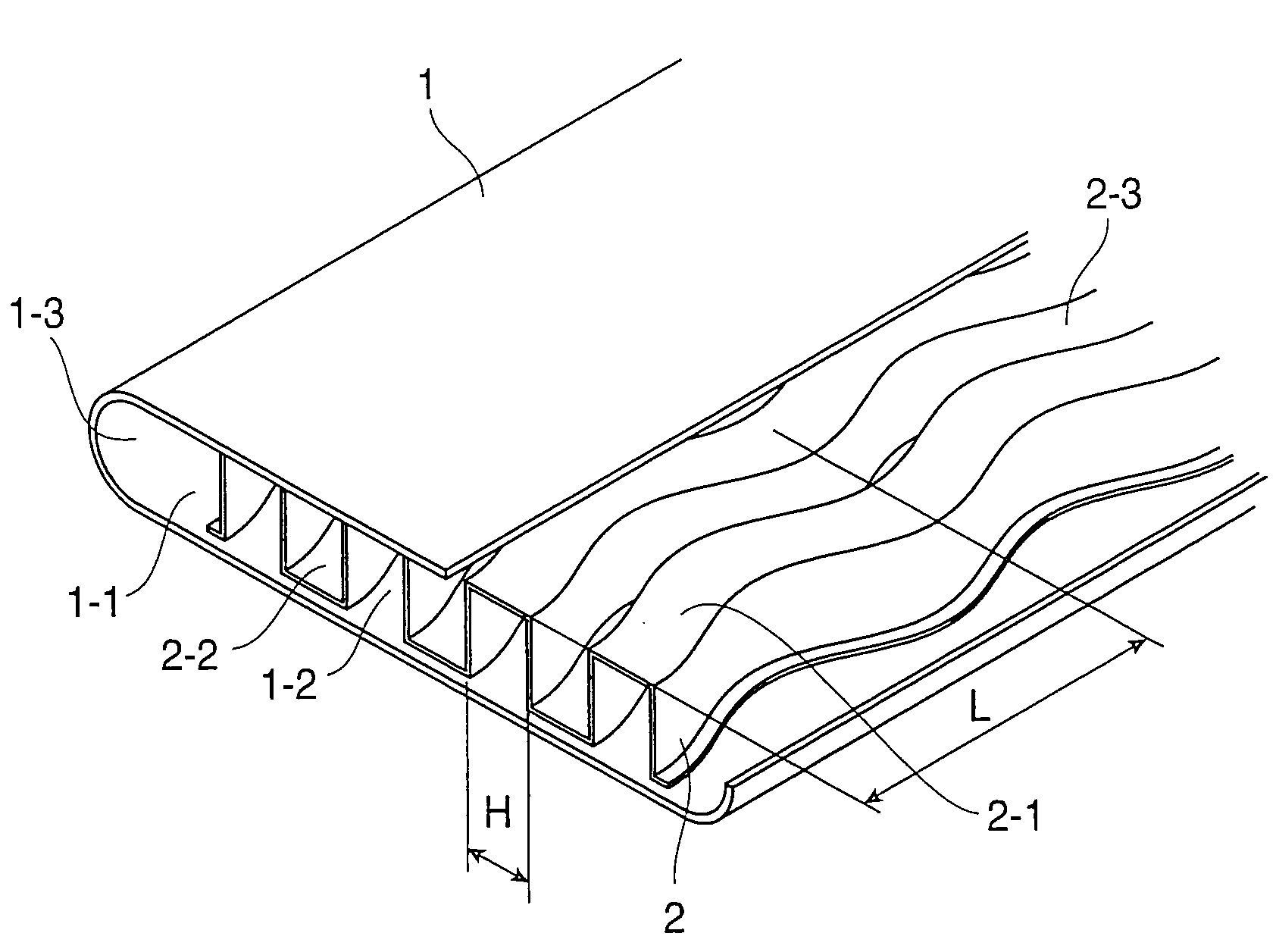
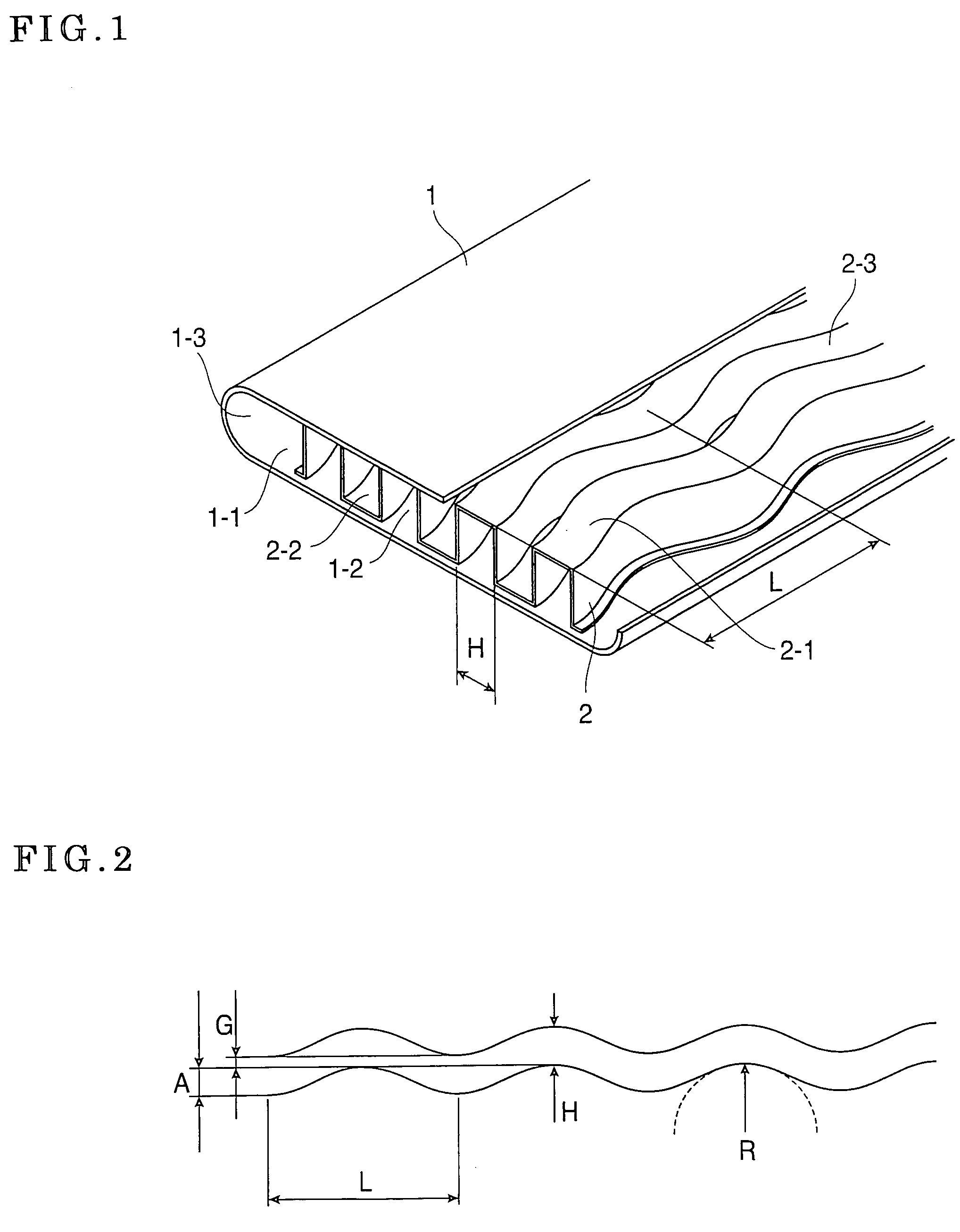
[0033]For a heat exchanger tube (heat exchanger tube) 1 in accordance with example 1 of the present invention, as showing the essential portion thereof enlargedly in FIG. 1, the heating tube 1 was obtained by inserting and integrally joining, by brazing, a corrugated fin structure 2 in and to an inner peripheral surface 1-1 of a flat tube. The corrugated fin structure 2 was formed by press forming a sheet material of SUS304L austenitic stainless steel having a thickness of 0.05 mm. The flat tube was formed of a stainless steel material of the same kind having a thickness of 0.5 mm so as to have a substantially elliptical cross-sectional shape. For the fin structure 2 of this example, as shown in FIG. 1, the cross section of the fin structure is formed into a substantially rectangular channel shaped waveform, and waveform meandering zigzagging to the right and left in the lengthwise direction is formed. At this time, by letting the wave width H of the channel-shaped waveform be 3.0 m...

example 2

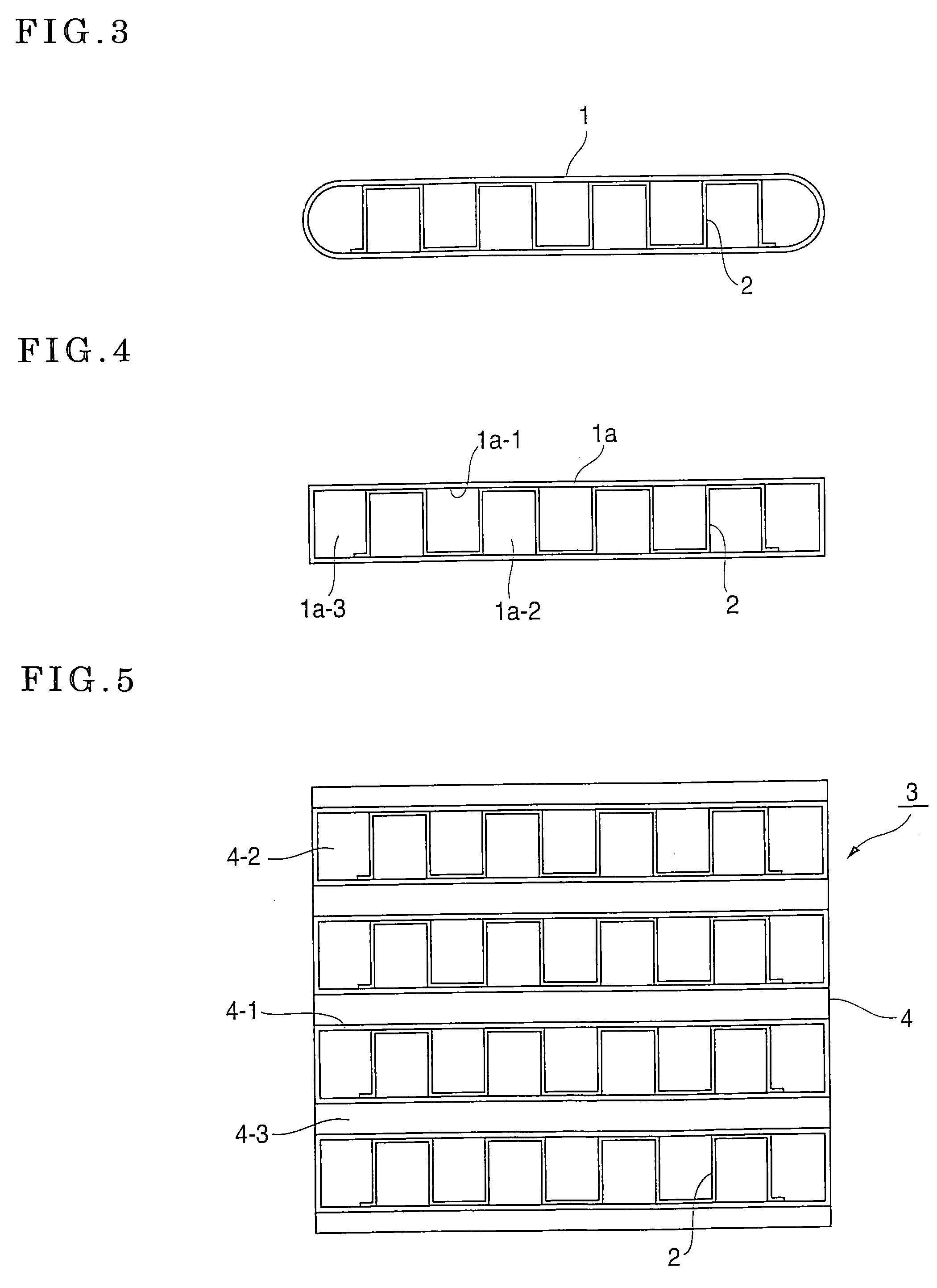
[0037]A heat exchanger tube 1a in which the corrugated fin structure 2 was incorporated substantially in the same way as in example 1 excluding that the cross-sectional shape of the flat heating tube 1a was rectangular was obtained. The EGR gas cooling system was subjected to a cooling performance test under the same conditions as those of example 1, and resultantly excellent results that were the same as those of example 1 were confirmed.

example 3

[0038]A laminated heat exchanger 3 in which a plurality of stages of EGR gas flow paths 4-2 having almost the same specifications as those of the flat heating tube 1a in example 2 and having a rectangular cross section was prepared. As shown in FIG. 5, a fin structure 2a formed in almost the same specifications as those of example 1 was inserted in the flow path 4-2. By integrally joining, by brazing, the fin structure 2a to a partitioning wall 4-1 that partitioned a cooling water flow path 4-3, a laminated heat exchanger 3 in which the corrugated fin structure 2a that was substantially the same as that of example 1 was incorporated in the gas flow path 4-2 was obtained. The obtained laminated heat exchanger 3 was subjected to a cooling performance test in the EGR gas cooling system under the same conditions as those of example 1, and resultantly excellent results that were the same as those of example 1 were confirmed.


PUM


Abstract

A heat exchanger tube has an inner peripheral surface serving as an exhaust gas flow path with a flat cross-sectional shape. A thin structure is incorporated in the heat exchanger tube and has a substantially rectangular channel-shaped waveform in cross section. The corrugated fin structure has a curved surface forming waveform meandering with a predetermined wavelength in the lengthwise direction. The wave width of the channel-shaped waveform is H, the wavelength of the waveform meandering in the lengthwise direction is L and the amplitude of the waveform meandering in the lengthwise direction is A. The heat exchanger tube is formed so that H / L is set at 0.17 to 0.20 and the ration (G / H) of a gap G determined by H−A to H is set at −0.21 to 0.19.

Description

TECHNICAL FIELD[0001]The present invention relates to a heat exchanger tube in what is called a shell-and-tube type exhaust gas cooling system. More particularly, it relates to a heat exchanger tube which is a heating tube having a flat cross-sectional shape that is arranged in plural numbers in a heat exchanger to form an exhaust gas flow path, incorporates a corrugated fin structure on the inner peripheral surface of the heating tube to enhance the heat exchange performance, and efficiently promotes heat exchange with a cooling medium flowing on the outside of the heating tube accomplished by flowing high-temperature exhaust gas in the exhaust gas flow path in the heating tube by making unique improvement on the corrugated fin structure to achieve a balance between the heat transfer performance brought by the corrugated fin structure and the loss of pressure.BACKGROUND ART[0002]A method in which some of exhaust gas is taken out of the exhaust system of a diesel engine, and is retu...

Claims


Application Information

Patent Timeline
Patent Type & Authority Patents(United States)
IPC IPC(8): F28F1/00F28F1/14F28F1/36
CPCF02M25/0737F28D7/1684F28F1/40F28F3/025F02M25/0714Y02T10/121F28D21/0003F02M26/11F02M26/32F28D1/047F28D7/08
Inventor USUI, SHOICHIROHAYASHI, KOICHIGOTO, TADAHIRO
Owner USUI KOKUSAI SANGYO KAISHA LTD
Why Eureka
Try Eureka