Mitigating interference in a signal

a signal and interference technology, applied in the field of structured signal receivers, can solve the problems of preventing a receiver, degrading the performance, and adding additional interference into the gps spectrum, and achieve the effect of being more robust to interferen

Inactive Publication Date: 2009-12-01
DATA FUSION CORP
View PDF106 Cites 218 Cited by
  • Summary
  • Abstract
  • Description
  • Claims
  • Application Information

AI Technical Summary

Benefits of technology

[0089]In another configuration, which is suboptimal, the receiver, during steady state operation, builds the interferer matrix with only the n highest-powered signals. N is the number of interferers and is limited by computational constraints. This configuration can determine the matrix S with a minimal of computational intensity and therefore allow for good performance with lower computational requirements.
[0093]Third, this invention can eliminate the necessity to determine the phase of the carrier of the interfering signals. Thus, interference mitigation in this invention is a phase-invariant process.
[0096]Sixth, this invention can make radio-navigation receivers more robust to interference. Embodiments of the invention can operate within a radio-navigation receiver as a signal processing technique. Additionally, embodiments of the present invention can be effectively used on analog or digital signals, and on RF or IF ranges. Thus, if predetermined and / or predictable structured interference is present in a wireless navigation signal, such interference can be removed and the resultant signal is passed to acquisition and tracking routines, as one skilled in the art will understand.
[0097]Seventh, the invention can be embodied in software, firmware or other programmable techniques within a GPS receiver having appropriate hardware to enable the signal processing performed by the present invention. Moreover, substantially all processing performed by the invention is embedded within the logic of one or more special purpose hardware components (e.g., chips, logic circuits, etc.), eliminating the need for programming such hardware components. Of course, hybrid embodiments that are between a substantially programmed embodiment and a substantially hardware embodiment are also within the scope of the present invention.

Problems solved by technology

When these transmitters broadcast augmentation signals in the GPS spectrum, additional interference is introduced into the GPS spectrum.
This structured interference is like noise to the receiver, degrading the performance and in some cases preventing a receiver from acquiring and tracking the satellites.
Moreover, the use of PLs violates one of the key assumptions behind the design of GPS.
Relatively strong PL signals may overwhelm satellite signals and jam a receiver.
Weak PL signals may be too feeble to allow receiver tracking.
The challenge associated with this variable range effect is known as the “near-far problem” in wireless communications.
Equally problematic is structured interference arising from sharing the GPS radio frequency spectrum with other users or from the encroachment of other users' signals on the GPS spectrum.
In another example, GPS jamming technologies may broadcast interference signals in the GPS spectrum.
These various RF systems introduce interference into existing RNSS systems either unintentionally or intentionally.
Another type of interference is self interference, which results when signals from a radio-navigation transmitter interfere with the reception of radio-navigation signals at the receiver.
This type of interference often occurs when a RNSS receiver and transmitter are located physically near (or identical to) each other.

Method used


Image

  • Mitigating interference in a signal
  • Mitigating interference in a signal
  • Mitigating interference in a signal

Examples


Embodiment Construction

Interference Mitigation Technique

[0111]Referring to the Wireless Signal Modeling description in the Terms and Definitions section above, Sharf and Friedlander (Sharf L. L., B. Friedlander, “Matched Subspace Detectors,” IEEE Trans Signal Proc SP-42:8, pp. 2146-2157, August 1994 incorporated fully herein by reference), showed that when the measurement noise variance is unknown, the uniformly most powerful (UMP) test for detecting contribution from H, while rejecting contributions from S is given by:

[0112]τ⁡(y)=yT⁢PG⁢yyT⁢PS⊥⁢PG⊥⁢PS⊥⁢y(3)

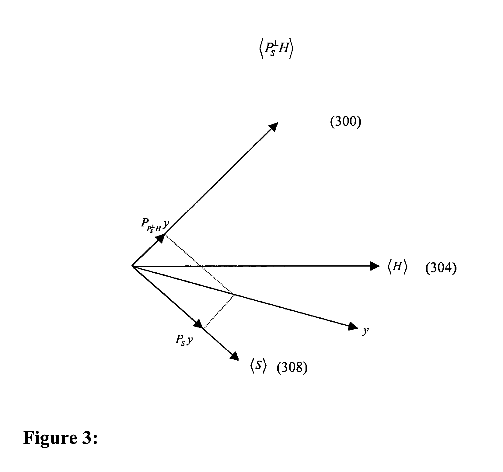
where:[0113]τ(y) is the Generalized Likelihood Ratio Test (GLRT). That is, the test provided by τ(y) is for determining whether the signal H (i.e., the target signal) is part of the composite signal y. More specifically, the signal H is declared present in y if τ(y) exceeds some appropriately defined threshold.[0114]PS=S(STS)−1 ST is the orthogonal projection operator matrix that would take an input and project it onto the space spanned by the columns o...


PUM


Abstract

A method and receiver are disclosed for mitigating or substantially canceling signal interference between signals detected at the receiver. Once a presumed interfering signal(s) is acquired, parameters are determined that allow the interferer(s) to be modeled. The phase invariance of the process eliminates the need to acquire the interferer's phase. An orthogonal projection (for projecting onto a detection subspace which is orthogonal to a subspace spanned by the interferer(s)) is applied to the composite of all signals (y) for thereby projecting y onto the detection subspace. The interference subspace is non-orthogonal to a representation of desired (but interfered) signal of the composite signals. With the receiver properly equipped to perform this projection operation, interfering signals, multipath, multipath-like, and structured jamming signals can be effectively diminished.

Description

CROSS-REFERENCE TO RELATED APPLICATIONS[0001]This application claims the benefits of U.S. Provisional Application Ser. No. 60 / 656,668 entitled “Mitigating Interference in a Signal,” filed Feb. 25, 2005, and hereby incorporated by reference.FIELD OF THE INVENTION[0002]The invention relates generally to the field of structured signal receivers and more particularly to a method for mitigating structured interference in a received composite signal by modeling the interference and then subsequently removing the interference from the signal.BACKGROUND OF THE INVENTION[0003]An example of a structured signal receiver is a Global Positioning System (GPS) receiver which is part of the United States' Global Positioning System (GPS), also known as a radio-navigation satellite system (RNSS). The GPS was established by the United States government, and employs a constellation of 24 or more satellites in well-defined orbits at an altitude of approximately 26,500 km. These satellites continually tr...

Claims


Application Information

Patent Timeline
Patent Type & Authority Patents(United States)
IPC IPC(8): G01S1/00G01S19/48
CPCH04B1/1027G01S5/145H03H17/0248H03H21/0025
Inventor KOBER, WOLFGANGKRUMVIEDA, ROBERT KENTREYNOLDS, LEWISKADLEC, STEVEN ALAN
Owner DATA FUSION CORP
Why Eureka
Try Eureka