
System and method for locating objects and communicating with the same

a technology of object and communication method, applied in the direction of direction finders using radio waves, frequency-division multiplexes, instruments, etc., can solve the problems of difficult noise extraction, low power transmission subject to signal corruption, and difficult to extract information from signals in the presence of such interference, so as to increase the signal-to-noise ratio of captured signals and lower levels.

Active Publication Date: 2010-01-12
SANTA MONICA SEMICON
View PDF31 Cites 98 Cited by
  • Summary
  • Abstract
  • Description
  • Claims
  • Application Information

AI Technical Summary

Benefits of technology

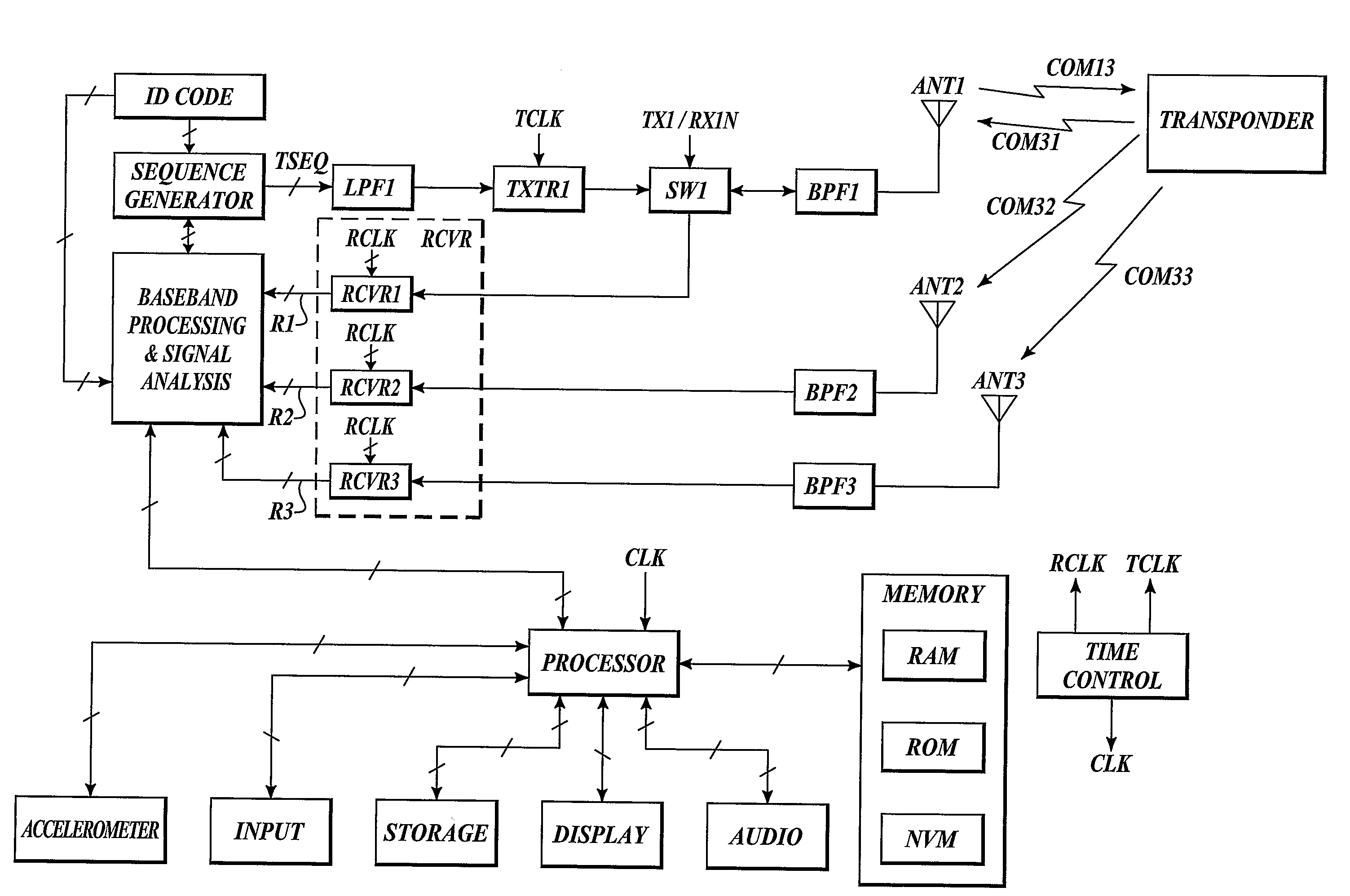
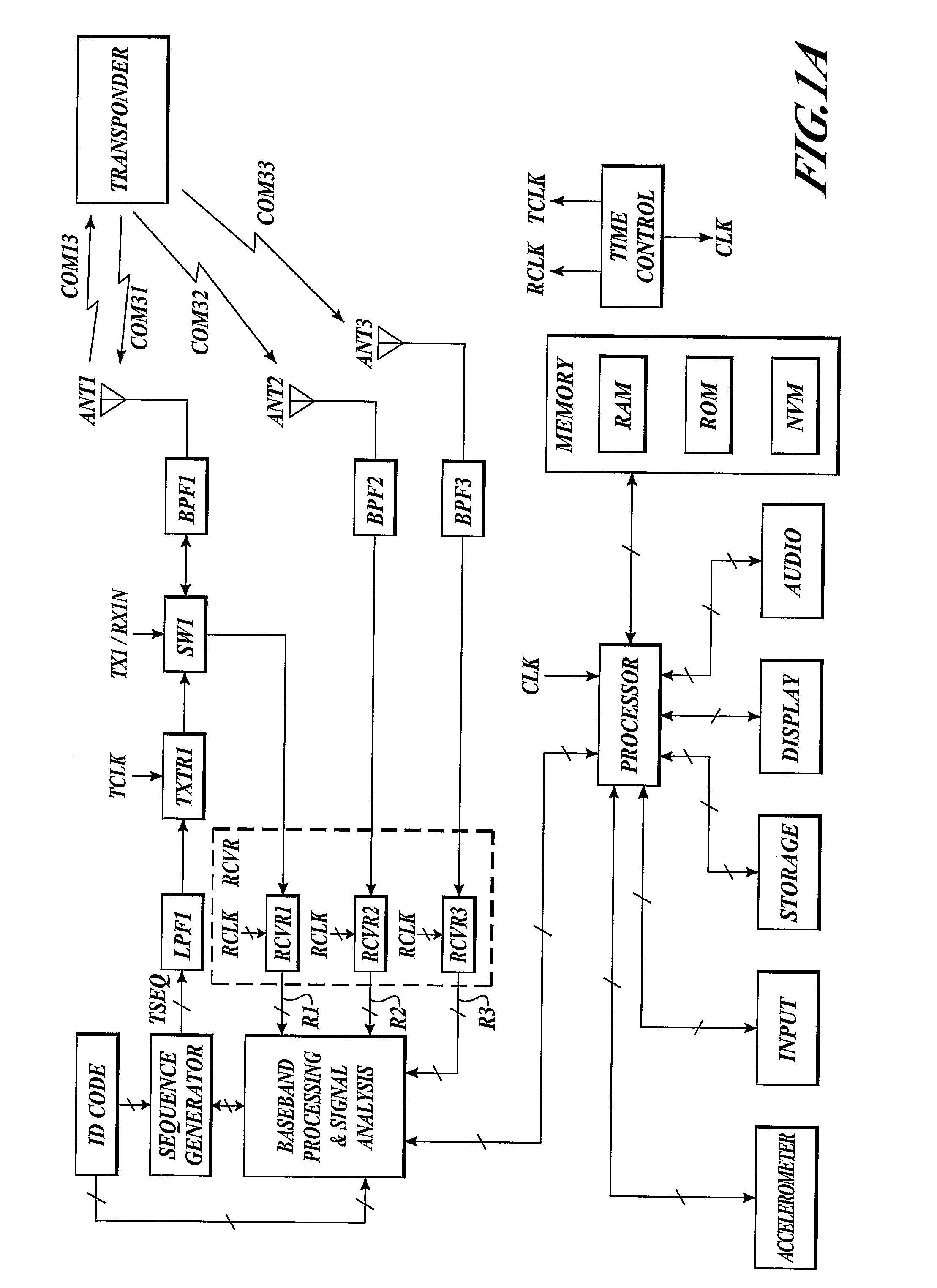
[0012]The presently described asymmetric transmission system can be configured such that the MT receives a relatively high power transmission of a structured signal from the RL, while the reply or acknowledgement transmission from the MT to the RL is a very low power transmission. An example MT is configured to operate in a very low power “inactive” mode or “sleep mode”, where the MT “activates” or “wake-ups” for brief intervals to listen for the transmission from the RL. The MT correlates each piece of its received structured signals to determine if these signals are coded with an identification code (ID Code) that is specifically associated with the MT. The MT also determines the precise frequency, timing, phase, and cadence for which a reply transmission can be transmitted back to the RL from the received structured signals. The reply transmission that is transmitted from the MT to the RL is a very low power transmission of short duration (a short structured signal) such that significant battery life is conserved. Although the reply transmission is a very low power transmission, the MT is arranged to utilize an integration and circular correlation technique to increase the signal-to-noise level of the captured reply transmission.
[0013]In the presently described system, a reply transmission signal is transmitted back to the RL from an MT, where the MT synthesizes timing, frequency, phase, and cadence for the reply transmission from signals that are received by the MT from the RL. The frequency of the reply transmission from the MT differs from the original frequency from the RL's transmission by a Doppler shift (ignoring other noise and minor error sources). As such, the RL can predict the reply transmission frequency with a very small margin of error. The potential uncertainty of the reply transmission frequency is small enough so that the phase rotation over several tens of transmission sequences is much less than one turn (one phase rotation through 360 degrees). This allows the RL to sample the reply transmission and add (or integrate), either in the analog domain or the digital domain, the respective samples from reply transmission sequence. Since noise sums as a square root and signal sums linearly, the signal-to-noise ratio for the captured signal is increased, allowing reception of a much lower level signal than would otherwise be the case without the use of exhaustive computation.

Problems solved by technology

Low power transmissions are subject to signal corruption due to noise, static, and signal interference.
Extracting information from a signal in the presence of such interference and noise is very difficult when the information signal is of the same order of magnitude as the noise sources.

Method used


Image

  • System and method for locating objects and communicating with the same
  • System and method for locating objects and communicating with the same
  • System and method for locating objects and communicating with the same

Examples


example remote

Locator (RL)

[0034]FIG. 1A illustrates an example RL that is arranged to communicate with an example MT. The MT is arranged (e.g., by a sleep timer) to wake up at pre-determined intervals and receive a coded transmission signal (e.g., COM13). The coded signals received and evaluated using a variety of signal processing methods such as digital signal processing, analog signal processing, Fast Fourier Transform (FFT), correlation, inverse FFT (IFFT) to name a few. The MT evaluates the received coded signals to determine if the signals are specifically identified with the MT (e.g., by a unique ID code). Through the various signal-processing functions, various internal signals and parameters are varied such that time, frequency and phase alignments for receiving and transmitting coded information are successively refined (e.g., through digital control mechanisms) for accurate processing. The MT, using as it's time base the Doppler shifted frequency of the signal from the RL, subsequently...

example micro -

Example Micro-Transponder (MT)

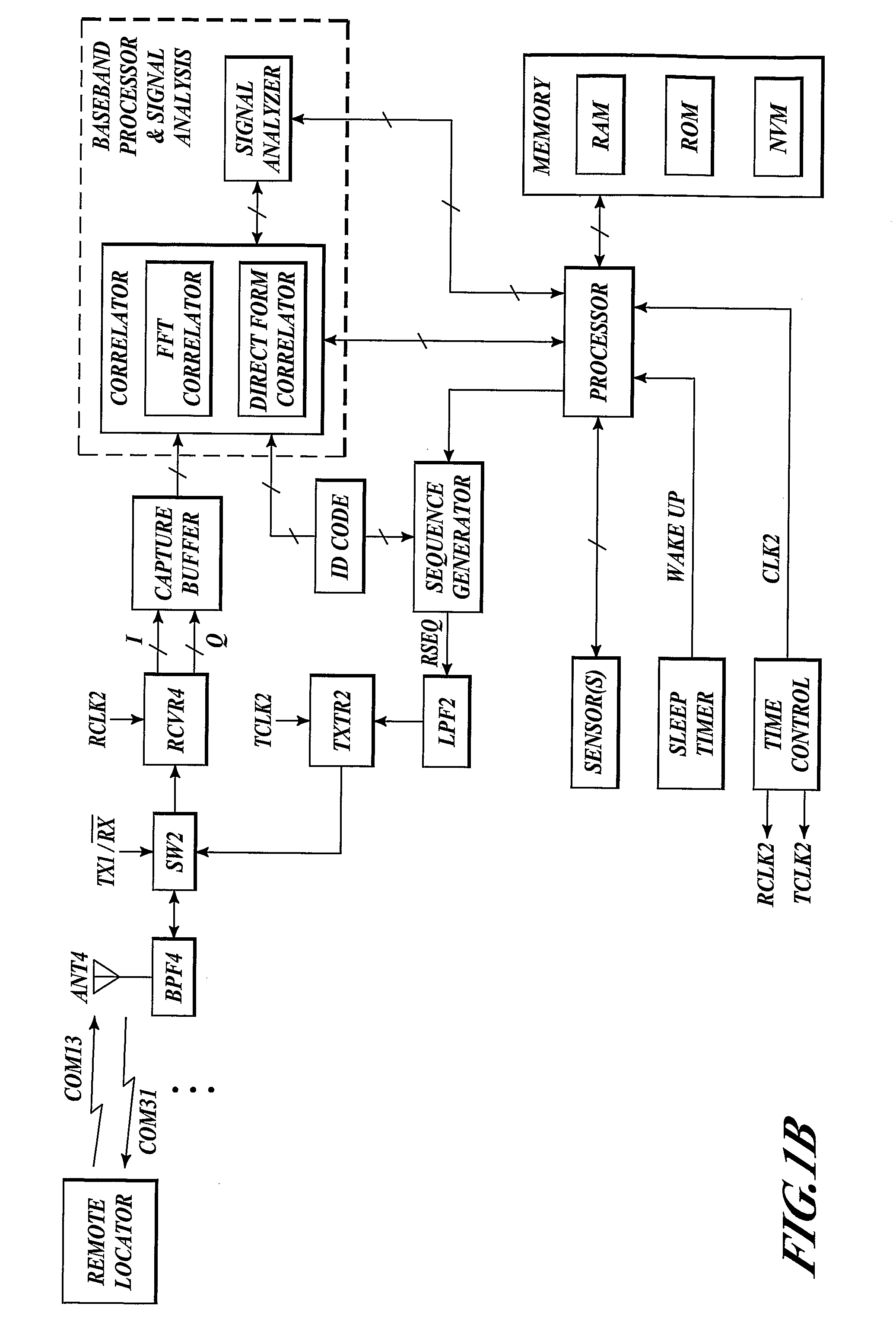
[0045]FIG. 1B illustrates an example MT that is arranged to communicate with a RL. The example MT may be placed in a wristband, a watch, sewn into an article of clothing, or implanted in a patient such as a with a bionic-type device. The MT is arranged to receive a coded transmission signal, such as previously described, from the RL with receiver RCVR4 via switch SW2 and antenna ANT4. Optionally, a band-limiting filter (e.g., BPF4) can be used to minimize interference from out-of-band signals in the receiver. The receiver demodulates the carrier frequency with oscillator signal ROSC2 and provides I and Q information, which is subsequently captured by a capture buffer. The capture buffer provides output signals in the form of data to an FFT correlator, which correlates the decoded transmission with the unique identifier (ID code). The processor is arranged to cooperate with memory similar to that previously described for the RL.

[0046]Various processing m...

example transmitter

[0053]FIG. 2 illustrates an example transmitter system. The transmitter system includes a crystal oscillator (XTAL OSC), a timing control circuit, a complex modulator, a pattern generator, an interpolation filter with timing control, integrators, and a complex cordic rotator.

[0054]The crystal oscillator is arranged to provide an oscillator signal as a clock signal (CLOCK) having a first phase (φ1) for the timing control circuit. In one example the crystal oscillator has a nominal frequency around 26.14 MHz, which can optionally be adjustable (e.g., via signal FREQ. TRIM). The oscillator can be a crystal-type oscillator, or any other oscillator that has a substantially stable oscillation frequency.

[0055]The timing control circuit includes a feedback control loop with an optional divider circuit that is arranged to synthesize a frequency. The control loop includes a phase detector, a low pass filter (LPF), a voltage controlled oscillator (VCO), and an optional divider circuit. The pha...


PUM


Abstract

Communication between a remote locator and a transponder is used to determine the relative position of the transponder. The transponder and locator each include a transmitter and a receiver. The locator transmits an inquiry in the form of a relatively powerful cyclically encoded signal with repetitive elements, uniquely associated with a target transponder. Periodically, each transponder correlates its coded ID against a possible inquiry signal, determining frequency, phase and framing in the process. Upon a match, the transponder transmits a synthesized response coherent with the received signal. The locator integrates multiple cyclical response elements, allowing low-power transmissions from the transponder. The locator correlates the integrated response, determines round-trip Doppler shift, time-of-flight, and then computes the distance and angle to the transponder. The transponder can be wearable, bionically implanted, or attached to, or embedded in, some object.

Description

FIELD OF THE INVENTION[0001]The present disclosure relates generally to a system and method of locating an object. More particularly, the present disclosure relates to a system and method for locating a living being. The living being may be located with a bionic device that is implanted therein for the purposes of tracking location.BACKGROUND OF THE INVENTION[0002]Some methods for locating an object are known in the art. A missing vehicle locator system is described in U.S. Pat. No. 5,418,736 issued to Bird. The vehicle locator system uses one or more GPS systems in conjunction with a GPS antenna, a receiver / transmitter, a telephone with associated antennas, and a modem mounted in a vehicle whose position is to be monitored. A paging request is issued and received by a paging responder in the vehicle. The paging request causes the modem to interrogate the GPS receiver to determine the current position of the vehicle. The current position of the vehicle is transmitted via a cellular ...

Claims


Application Information

Patent Timeline
IPC IPC(8): G01S13/74G01S13/06G01S13/08G01S13/00
CPCG01S13/765G01S13/878
Inventor KARR, LAWRENCE J.
Owner SANTA MONICA SEMICON
Learn More