Cardiac valve annulus reduction system

a technology of annulus reduction and valve, applied in the field of medical devices, can solve the problems of restricted blood flow, backward leakage of blood, and valve function proper function,

Active Publication Date: 2010-02-02
MEDTRONIC VASCULAR INC
View PDF24 Cites 143 Cited by
  • Summary
  • Abstract
  • Description
  • Claims
  • Application Information

AI Technical Summary

Problems solved by technology

Heart valves, such as the mitral valve, tricuspid, aortic and pulmonic valves, are sometimes damaged by disease or by aging, which can cause problems with the proper function of the valve.
Heart valve problems generally take one of two forms: stenosis, in which a valve does not open completely or the opening is too small, resulting in restricted blood flow; or insufficiency, in which blood leaks backward across the valve that should be closed.
In common practice, repair or replacement requires open-heart surgery with its attendant risks, expense, and extended recovery time.
Open-heart surgery also requires cardiopulmonary bypass with risk of thrombosis, stroke, and infarction.
Any one or more of the mitral valve structures, i.e., the anterior and posterior leaflets, the chordae, the papillary muscles or the annulus may be compromised by damage from disease or injury, causing the mitral valve insufficiency.
Typically, in cases where there is mitral valve insufficiency, there is some degree of annular dilation resulting in mitral valve regurgitation.
Thus, without correction, the mitral valve insufficiency may lead to disease progression and / or further enlargement and worsening of the insufficiency.
However, the valve replacement may result in a number of complications including a risk of endocarditis.
Although mitral valve repair and replacement can successfully treat many patients with mitral valve insufficiency, techniques currently in use are attended by significant morbity and mortality.
Those patients undergoing such techniques may have scarring retraction, tears or fusion of valve leaflets as well as disorders of the subvalvular apparatus.
While the coronary sinus implant provides a less invasive treatment alternative, the placement of the prosthesis within the coronary sinus may be problematic for a number of reasons.
The coronary sinus on a particular individual may not wrap around the heart far enough to allow enough encircling of the mitral valve.
Also, leaving a device in the coronary sinus may result in formation and release of thrombus that may pass into the right atrium, right ventricle and ultimately into the lungs, possibly causing a pulmonary embolism.
Another disadvantage is that the coronary sinus is typically used for placement of a pacing lead, which may be precluded by the previous placement of a prosthesis in the coronary sinus.

Method used


Image

  • Cardiac valve annulus reduction system
  • Cardiac valve annulus reduction system
  • Cardiac valve annulus reduction system

Examples


Embodiment Construction

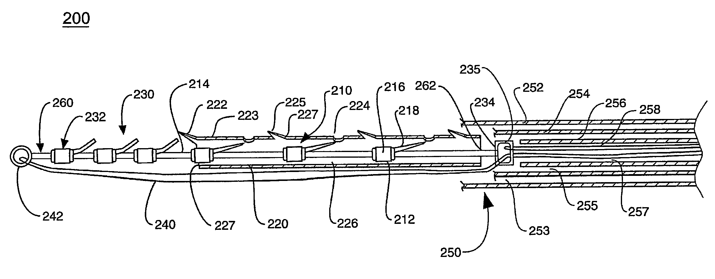
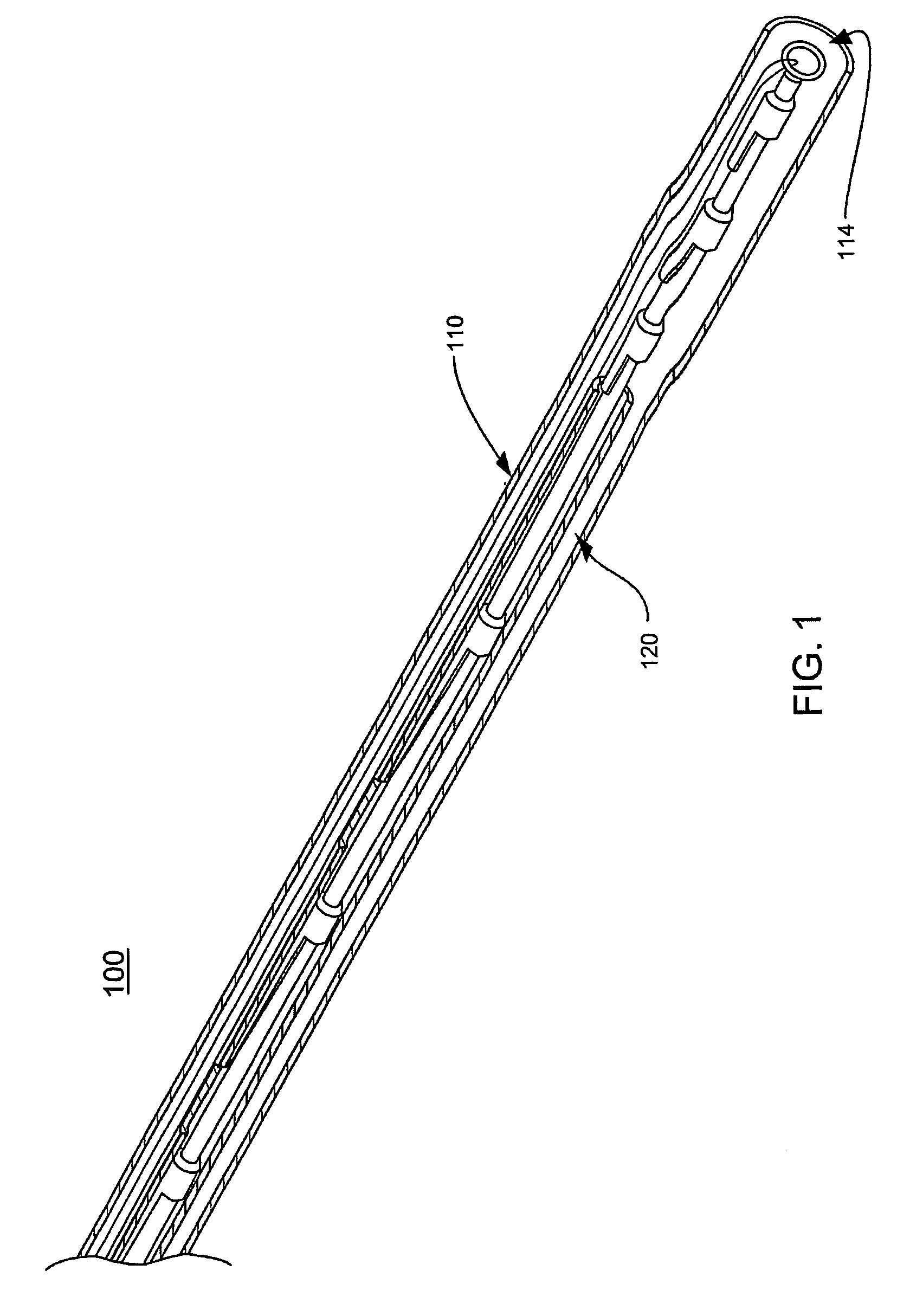
[0031]FIG. 1 shows a cardiac valve annulus reduction assembly and a delivery system in accordance with the present invention. Annulus reduction delivery system 100 includes delivery catheter 110 having lumen 114 there through. Annulus reduction assembly 120 is disposed within lumen 114 and is described in more detail below.

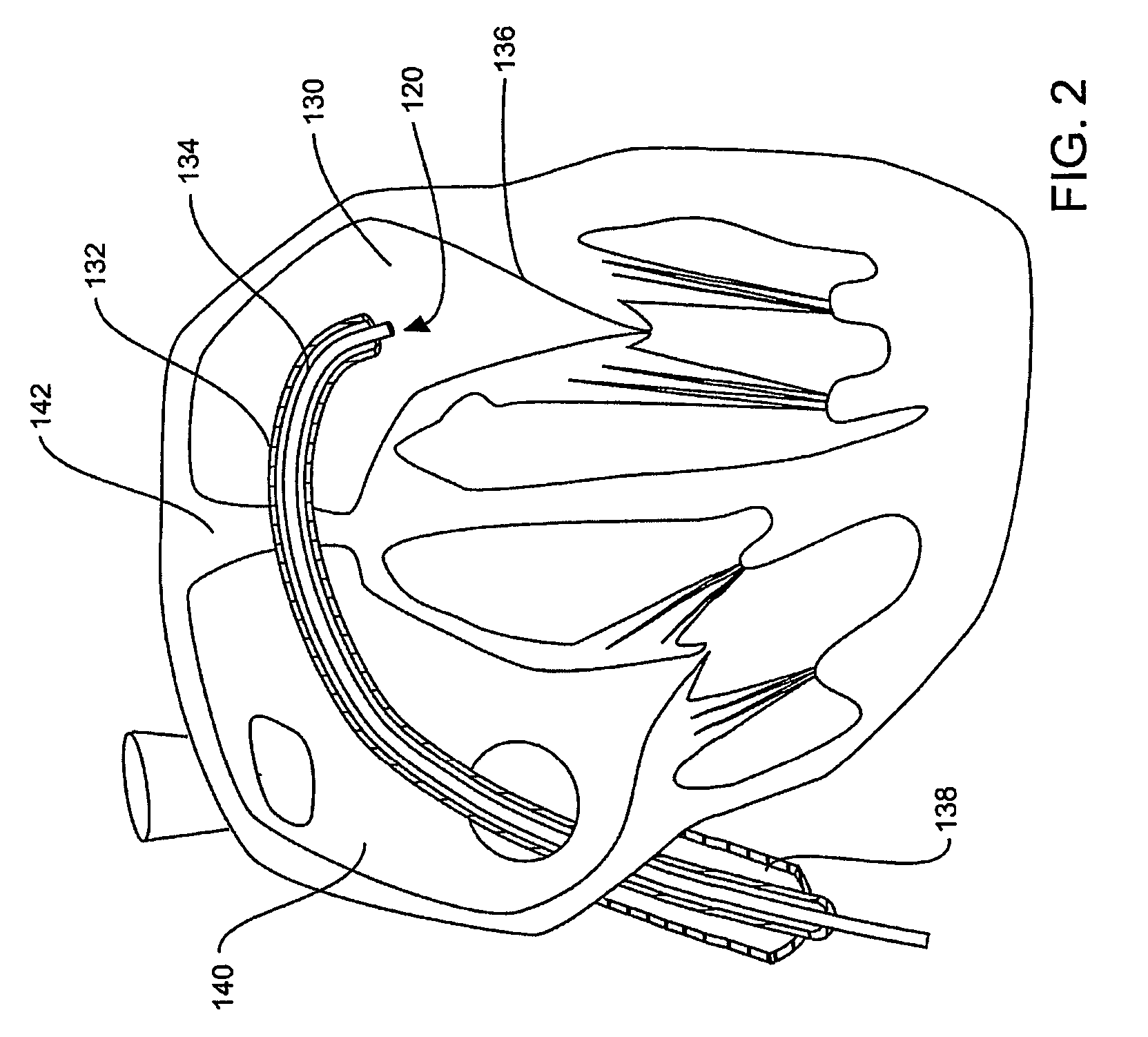
[0032]FIG. 2 shows a delivery system 100 positioned via a femoral venous transeptal approach with the system distal end lying within the left atrium. As shown, annulus reduction assembly 120 has not been deployed from delivery catheter 110. Annulus reduction assembly 120 may be delivered via percutaneous transluminal techniques or via surgery using open-chest or port access modalities.

[0033]For the exemplary case of mitral valve remodeling shown in FIGS. 1 and 2, annulus reduction assembly 120 is implanted from the left atrium 130. An elongate element 132, such as a catheter having lumen 134, is first inserted to provide a path for annulus reduction delivery syste...


PUM


Abstract

A catheter-based, annulus reduction device and system for cardiac valve repair and method of using the same. The system is usable for treating mitral valve regurgitation and comprises a catheter, a reduction ring carried within the catheter, the reduction ring including a plurality of exit ports formed in a side wall of the reduction ring and filament received in the reduction ring. The filament includes a plurality of radially extendible barbs corresponding to the sidewall openings. The reduction ring carrying the filament is deployed adjacent a mitral valve annulus and the filament is translated relative to the reduction ring to deploy the barbs through the exit ports and into the annulus and to further translate the reduction ring with deployed barbs to reshape the annulus.

Description

TECHNICAL FIELD[0001]The technical field of this disclosure is medical devices, particularly, a cardiac valve annulus reduction system and method of using the same.BACKGROUND OF THE INVENTION[0002]Heart valves, such as the mitral valve, tricuspid, aortic and pulmonic valves, are sometimes damaged by disease or by aging, which can cause problems with the proper function of the valve. Heart valve problems generally take one of two forms: stenosis, in which a valve does not open completely or the opening is too small, resulting in restricted blood flow; or insufficiency, in which blood leaks backward across the valve that should be closed. Valve replacement may be required in severe cases to restore cardiac function. In common practice, repair or replacement requires open-heart surgery with its attendant risks, expense, and extended recovery time. Open-heart surgery also requires cardiopulmonary bypass with risk of thrombosis, stroke, and infarction.[0003]In various types of cardiac di...

Claims


Application Information

Patent Timeline
Patent Type & Authority Patents(United States)
IPC IPC(8): A61F2/24A61B17/00A61B17/04A61B17/06A61F2/04
CPCA61B17/00234A61B17/0401A61F2/2445A61B2017/00243A61B2017/00783A61B2017/0414A61B2017/0496A61B2017/06052A61B2017/06176A61F2002/30545A61F2220/0016A61F2250/001
Inventor DOUK, NAREAKRAFIEE, NASSERBLOOM, ELIOTFOGG, DOUGLAS A.HUYNH, RANYBARONE, DAVID D.
Owner MEDTRONIC VASCULAR INC
Why Eureka
Try Eureka