Thermal barrier coating material and method for production thereof, gas turbine member using the thermal barrier coating material, and gas turbine

a technology of thermal barrier coating and thermal barrier coating, which is applied in the direction of machines/engines, waterborne vessels, natural mineral layered products, etc., can solve the problems of increased thermal conductivity of topcoat, reduced peeling resistance, and difficulty in application to large-scale gas turbines or the like. , to achieve the effect of reducing peeling resistance, reducing cost, and adequate durability

Inactive Publication Date: 2010-02-02
MITSUBISHI HEAVY IND LTD
View PDF18 Cites 11 Cited by
  • Summary
  • Abstract
  • Description
  • Claims
  • Application Information

AI Technical Summary

Benefits of technology

[0012]Another object of the first aspect of the invention is to provide a gas turbine member which is adequately durable even in the environments of higher temperature than those of conventional temperatures, by an application of the thermal barrier coating material which provides both a higher thermal barrier property and a higher peeling resistance.
[0013]An object of the second aspect of the invention is to provide a thermal barrier coating material which provides both a higher thermal barrier property and a higher peeling resistance in comparison to the material in which YSZ is used as a topcoat.
[0014]Another object of the second aspect of the invention is to provide a gas turbine member that is adequately durable even in the environments of higher temperature than those of conventional temperatures, by an application of the thermal barrier coating material which provides both a higher thermal barrier property and a higher peeling resistance in comparison to the material in which YSZ is used as a topcoat.
[0015]An object of the third aspect of the invention is to provide, as a TBC raw material for thermal spraying, a stabilized zirconia powder being high in stability wherein particles of a rare earth oxide such as yttria are mixed uniformly with zirconia particles.
[0016]In achieving the above objects, the present inventors considered that the topcoat of a porous ceramic is effective for securing a higher thermal barrier property. The present inventors also considered that microcracks that extend in the thickness direction in the ceramic layer are effective for securing a higher peeling resistance. As a result of diligent research, they came to complete the first aspect of the invention.
[0017]The present inventors also paid attention to partially stabilized ZrO2 which is partially stabilized by Yb2O3 (hereinafter referred to as “YbSZ”). Since YbSZ has a 10 to 20% greater linear expansion coefficient than YSZ or DySZ, it presents the possibility of providing a higher peeling resistance. That is, the present inventor considered that a composite material of DySZ and YbSZ, DySZ being higher in thermal barrier effect than YSZ and YbSZ being higher in peeling resistance than YSZ, can be used effectively as a topcoat and came to complete the second aspect of the invention as a result of diligent research.

Problems solved by technology

However, since the application process for the electron beam physical vapor deposition requires a large amount of time, application to a large-scale gas turbine or the like is difficult in terms of cost.
Since the thermal conductivity of the obtained film becomes approximately 30% greater than that of porous ceramic, the film thickness must be made large, thus presenting a further difficulty in use.
As for the method of laminating the ceramic layer while forming the microcracks by thermal spraying, the formation of the microcracks requires a dense ceramic layer, leading to the problem that the topcoat is increased in thermal conductivity and thus lowered in thermal barrier property.
Furthermore, the microcracks are frequently formed not only in the thickness direction but also in the layer direction, leading to the problem that the ceramic layer peels in layers.
However, in these methods, the mixing of zirconia and yttria is not uniform due to the diffusion rate of zirconia being slower and the like.
Thus, it is difficult to produce completely stabilized zirconia.

Method used


Image

  • Thermal barrier coating material and method for production thereof, gas turbine member using the thermal barrier coating material, and gas turbine
  • Thermal barrier coating material and method for production thereof, gas turbine member using the thermal barrier coating material, and gas turbine
  • Thermal barrier coating material and method for production thereof, gas turbine member using the thermal barrier coating material, and gas turbine

Examples


examples 1 to 15

[0115]The sample Nos. 1 to 15 described below were prepared.

(Sample No. 1)

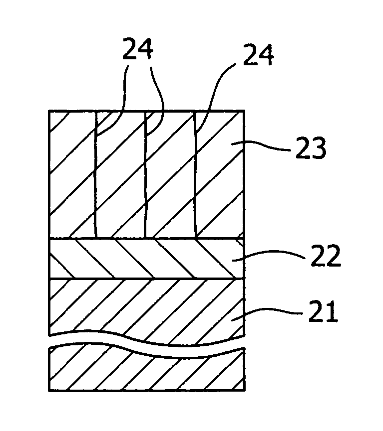
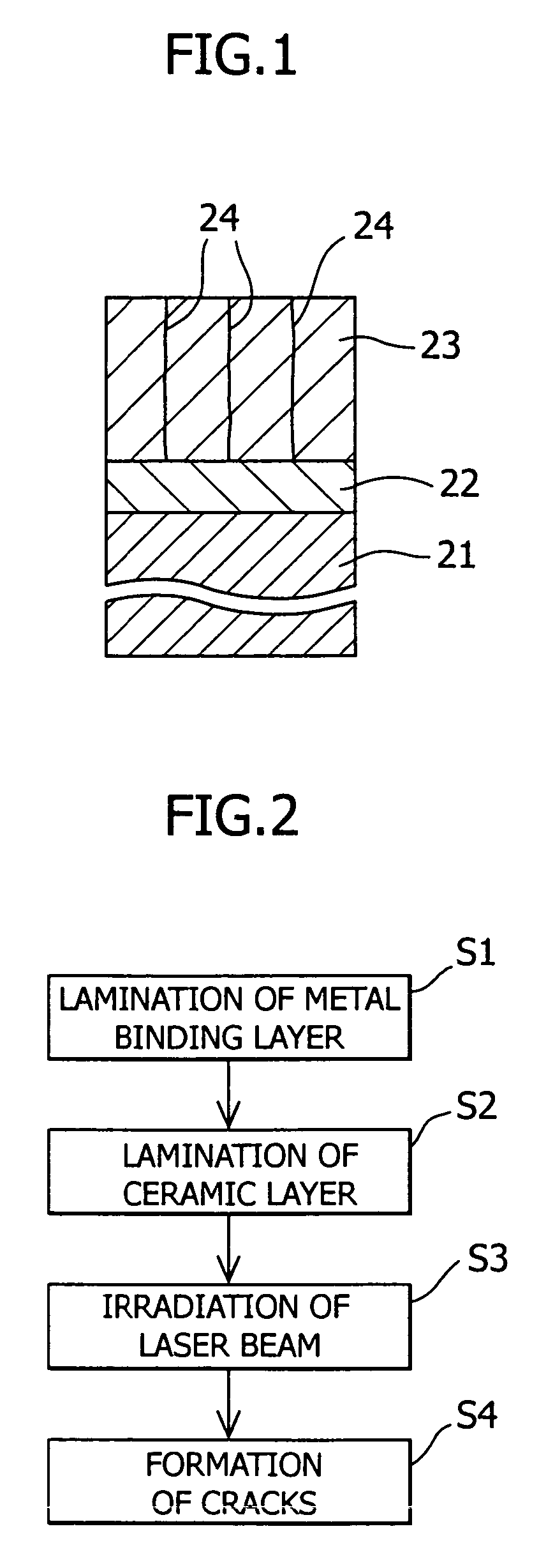
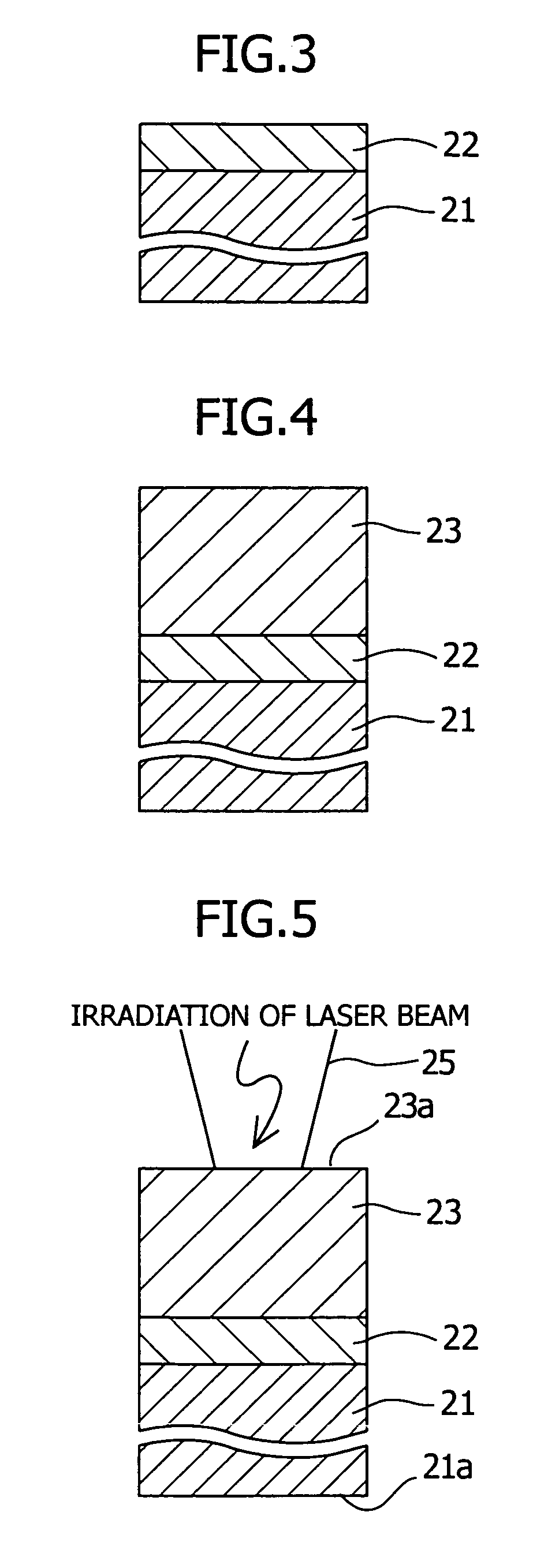
[0116]The surface of the base material was grid-blasted with Al2O3 particles and put in a state suitable for low pressure plasma spraying. A CoNiCrAlY alloy layer was then formed to a thickness of 0.1 mm by the low pressure plasma spraying. A ceramic layer comprising porous and partially stabilized ZrO2, which had been partially stabilized by 8 wt % of Y2O3 as an additive, was then formed to a thickness of 0.5 mm by atmospheric pressure plasma spraying. Then, while cooling the rear surface of the base material, the top surface of the ceramic layer was subject to 30 seconds×100 times of irradiations of a laser beam from a carbon dioxide laser. Thus, the heat cycle was repeated. In this process, the top surface of the ceramic layer was heated to a maximum temperature of 1400° C. The irradiation area per spot of the laser beam was 177 mm2 (beam diameter: 15 mm). The entire sample was then cooled to room temperatu...

examples 1 to 136

[0141]Sample Nos. 101 to 136, described below, were prepared.

(Sample No. 101)

[0142]The top surface of the base material was grid-blasted with Al2O3 grains and put in a state suitable for low pressure plasma spraying. A CoNiCrAlY alloy layer was then formed to a thickness of 0.1 mm by the low pressure plasma spraying. A ZrO2-10 wt % Dy2O3-0.1 wt % Yb2O3 layer was then formed to a thickness of 0.5 mm by atmospheric pressure plasma spraying.

(Sample No. 102)

[0143]The top surface of the base material was grid-blasted with Al2O3 grains and put in a state suitable for low pressure plasma spraying. A CoNiCrAlY alloy layer was then formed to a thickness of 0.1 mm by the low pressure plasma spraying. A ZrO2-10 wt % Dy2O3-6 wt % Yb2O3 layer was then formed to a thickness of 0.5 mm by atmospheric pressure plasma spraying.

(Sample No. 103)

[0144]The top surface of the base material was grid-blasted with Al2O3 grains and put in a state suitable for low pressure plasma spraying. A CoNiCrAlY alloy la...


PUM

PropertyMeasurementUnit
specific surface areaaaaaaaaaaa
porosityaaaaaaaaaa
thicknessaaaaaaaaaa

Abstract

A thermal barrier coating material, containing a metal binding layer laminated on a base material and a ceramic layer laminated on the metal binding layer, the ceramic layer comprising partially stabilized ZrO2 which is partially stabilized by additives of Dy2O3 and Yb2O3.

Description

TECHNICAL FIELD[0001]The invention relates to a thermal barrier coating material, a method of production thereof, and a gas turbine member and a gas turbine to which the thermal barrier coating material is applied, and relates to useful arts which are applicable, for example, to thermal barrier coatings for rotor blades and stator blades of industrial gas turbines as well as for combustors and other parts used in high-temperature environments.BACKGROUND ART[0002]Since high-temperature parts, such as rotor blades and stator blades of industrial gas turbines, and flame tubes, tail pipes, and split rings of combustors, etc., are used in high-temperature environments, they are generally provided with a thermal barrier coating on the surface.[0003]FIG. 11 is a sectional view of a conventional thermal barrier coating.[0004]The conventional thermal barrier coating film is arranged by laminating a metal binding layer 12 of MCrAlY alloy on a base material 11 of a rotor blade or the like and ...

Claims


Application Information

Patent Timeline
Patent Type & Authority Patents(United States)
IPC IPC(8): B32B15/04B32B18/00C23C4/08C23C4/10C23C4/18C23C28/00F01D5/28
CPCC23C4/085C23C4/105C23C4/18F01D5/288C23C28/3215C23C28/3455F05D2230/40F05D2230/31F05D2230/312F05D2230/311F05D2230/90F05D2300/2118C23C4/11C23C4/073
Inventor TORIGOE, TAIJIMORI, KAZUTAKAOKADA, IKUOAOKI, SUNAOTAKAHASHI, KOUJIOHARA, MINORUHIRATA, TAKEHIKO
Owner MITSUBISHI HEAVY IND LTD
Why Eureka
Try Eureka