Inductive pulse forming network for high-current, high-power applications

a technology of inductive pulse forming network and high-current, which is applied in the direction of pulse generator, pulse technique, pulse train generator, etc., can solve the problems of inability to directly supply power to the railgun by the ship bus, dangerous electrical conditions of the use of high-voltage capacitor in the capacitive pfn, and the failure of many low-voltage capacitors in series to supply the requisite high current, etc., to achieve the effect of increasing the overall curren

Inactive Publication Date: 2010-03-09
THE UNITED STATES OF AMERICA AS REPRESENTED BY THE SECRETARY OF THE NAVY
View PDF20 Cites 8 Cited by
  • Summary
  • Abstract
  • Description
  • Claims
  • Application Information

AI Technical Summary

Benefits of technology

[0023]Further, in accordance with the principles of the present invention, in one embodiment an inductive PFN system is provided that includes more than one inductive PFN coupled in parallel to a single load to provide sequential high-current pulses that provide increased overall current to the load during a single use. Said another way, a first inductive PFN embodiment and at least one addition inductive PFN embodiment are coupled in parallel to a single load to form an inductive PFN system that provides sequential high-current pulses used to form a desired waveform. Alternatively, an inductive PFN system including multiple inductive PFN embodiments coupled in parallel, provides repeated uses of the load in a more rapid succession than is provided by multiple chargings of a single inductive PFN. In yet another alternative, individual inductive PFNs of an inductive PFN system may be connected to physically discrete and electrically isolated rail segmen

Problems solved by technology

This large peak power requirement made the ship's bus incapable of directly supplying power to the railgun.
The use of high-voltage capacitors in a capacitive PFN presented dangerous electrical conditions.
However, putting many low-voltage (2-50 Volts) capacitors in series to supply the requisite high current did not work because the available energy was reduced and the equivalent series resistance (ESR) of the series low-voltage capacitors prevented extraction of the high currents required to drive the railgun.
Prior art designs for high-voltage capacitor PFNs used with railguns and other electromagnetic launchers such as aircraft carrier electromagnetic aircraft launch systems and electromagnetic aircraft recovery systems, are excessively heavy and bulky

Method used


Image

  • Inductive pulse forming network for high-current, high-power applications
  • Inductive pulse forming network for high-current, high-power applications
  • Inductive pulse forming network for high-current, high-power applications

Examples


Embodiment Construction

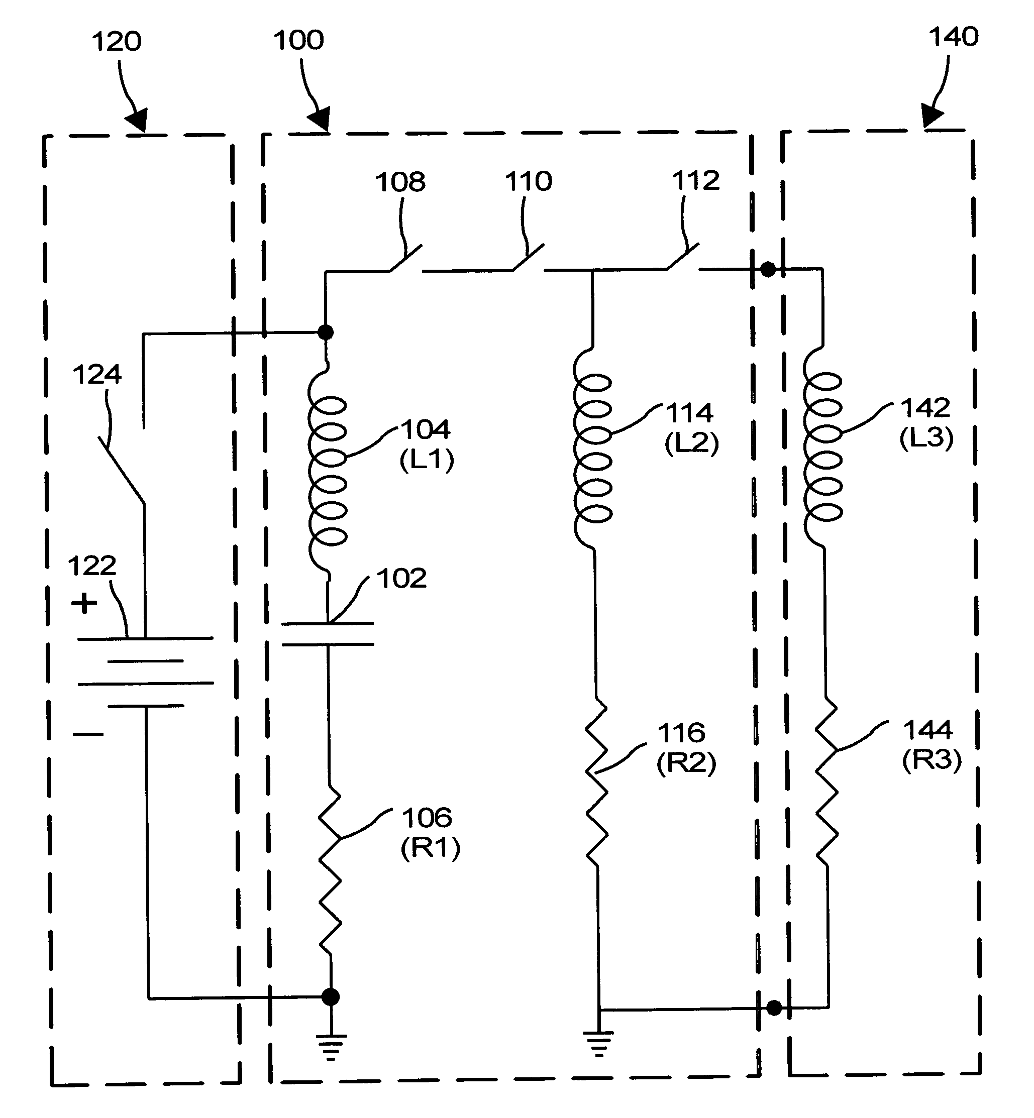
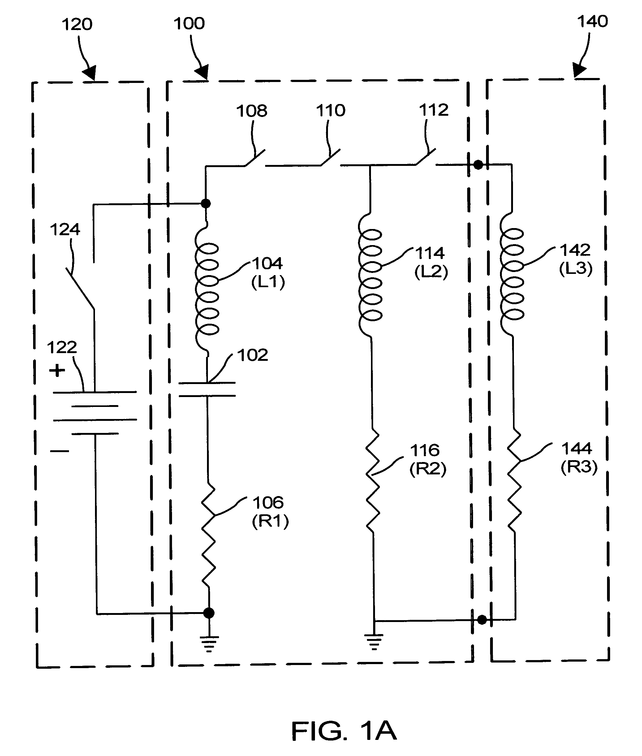
[0034]In accordance with one embodiment of the present invention, in FIG. 1A, an inductive PFN 100 stores energy delivered from an outside prime power supply 120 in the electric field of a network capacitor 102 that is subsequently converted to energy stored in the magnetic field of a network inductor 114. Through a series of switches, the energy stored in the magnetic field of the network inductor is delivered as a high-current pulse to a connected load.

[0035]More particularly, FIG. 1A is a circuit diagram of one embodiment of inductive PFN 100 of the present invention for use as a high-current power supply in a railgun. Inductive PFN circuit 100 includes a network capacitor 102. As described above, associated with any real network capacitor 102 is a resistance R1, represented by network capacitor equivalent resistor 106, and an inductance L1, represented by network capacitor equivalent inductor 104, characterizing the departure of network capacitor 102 from an ideal capacitor. Net...


PUM


Abstract

An inductive pulse forming network stores electrical energy delivered from an outside prime power supply in the electric field of a low-voltage, high-energy density network capacitor. Through timed actuation of a series of one or more switches, the energy stored in the electric field of the network capacitor is subsequently converted to electrical energy stored in the magnetic field of a network inductor. The energy stored in the network inductor supplies high-current, high-power electrical energy to drive an electromagnetic launcher such as a railgun.

Description

BACKGROUND OF THE INVENTION[0001]1. Field of the Invention[0002]The present invention generally relates to pulse forming networks. More particularly, the present invention relates to high-current, high-power, inductive pulse forming network for use with electromagnetic launchers such as railguns and electromagnetic aircraft launchers.[0003]2. Description of the Related Art[0004]A Pulse forming network (PFN) is an electrical circuit or device that provides a high-power, short-duration pulse of electrical energy of desired waveform. The elements of a PFN are electrically coupled and configured to make a transient current pulse of specific waveform across a load when a load switch is closed.[0005]PFNs have applications, well known to those of skill in the art, in high-power, short-duration power supplies used, for example, in pulsed lasers, pulsed magnetic plasma confinement machines, high-powered microwave weapons, pulsed accelerators for flash x-ray and pulsed electron beam machines,...

Claims


Application Information

Patent Timeline
IPC IPC(8): H03K3/00F41B6/00
CPCF41B6/006H03K3/53
Inventor MAIER, II, WILLIAM BRYAN
Owner THE UNITED STATES OF AMERICA AS REPRESENTED BY THE SECRETARY OF THE NAVY
Why Eureka
Try Eureka