Apparatus for fabricating coating and method of fabricating the coating

a technology of apparatus and coating, which is applied in the field of apparatus for fabricating coating and method of fabricating coating, can solve the problems of inability to perform, improve hardness and adhesion lack of long-term reliability of protective film of hard carbon coating, etc., and achieves the effect of preventing flakes from forming, facilitating film fabrication on the cathode side, and facilitating the invention

Inactive Publication Date: 2010-04-20
SEMICON ENERGY LAB CO LTD
View PDF175 Cites 25 Cited by
  • Summary
  • Abstract
  • Description
  • Claims
  • Application Information

AI Technical Summary

Benefits of technology

[0015]Another object of the invention is to provide a method of fabricating a hard carbon coating which is fine, has high hardness and adhesion and reduces the number of pin-holes formed therein as a protective film of a magnetic recording medium.
[0067]Accordingly, film fabrication on the cathode side can be restrained and occurrence of flakes can be restrained. Further, the maintenance duration for the apparatus can be extended, thereby greatly contributing to an improvement in through-put and a reduction in the costs. In the case of a super LSI process or the like, it causes contamination, however, in fabricating a carbon film as in the present invention, there does not arise a problem such as contamination. When the film which constitutes an object is electrically conductive, a film can be disposed not on the cathode side but only on the anode side. The present invention is effective even in such a case.

Problems solved by technology

However, according to the experiments of the inventors, it has been ascertained that the hard carbon coating having the pin-holes therein lacks long-term reliability as a protective film because moisture is infiltrated into the pin-holes.
Also, it has been ascertained that improvements in hardness and adhesion of the hard carbon coating and the prevention of generation of the pin-holes are not always performed together.
Recently, there is a tendency to heighten the density of the magnetic recording medium.
In general, a carbon film with a high hardness cannot be fabricated on a grounded electrode (anode) side.
Therefore, if such an object is in contact with the cathode electrode, the object constitutes a part of the electrode, and therefore a high-frequency electric field is leaked as a result of which discharge occurs in an undesired region.
There is a high possibility that the organic resin film constituting the object is damaged by such discharge, causing a problem on the stability and reliability of production.
Furthermore, fabricating the hard carbon film which is a protective film at the same time as the roll to roll type magnetic layer fabricating process is impossible because the carbon film forming speed is low.

Method used


Image

  • Apparatus for fabricating coating and method of fabricating the coating
  • Apparatus for fabricating coating and method of fabricating the coating
  • Apparatus for fabricating coating and method of fabricating the coating

Examples


first embodiment

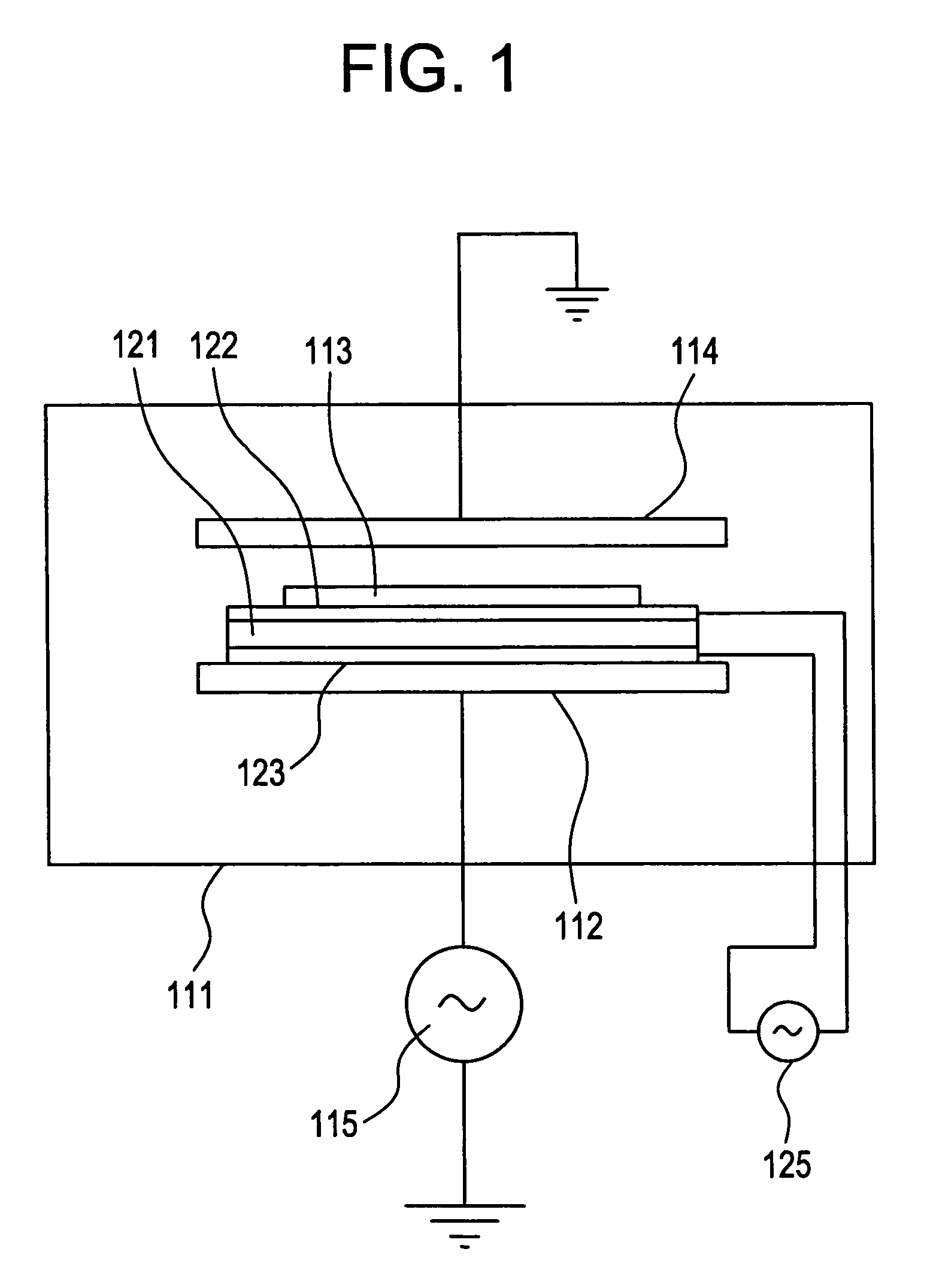
[0085]FIG. 1 is a diagram showing a structure of a plasma CVD apparatus for fabricating a hard carbon coating on a surface of formation while the object 113 is ultrasonic-vibrated.

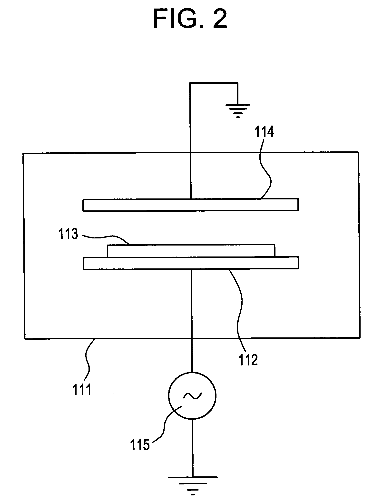
[0086]The plasma CVD apparatus includes a pair of electrodes 112 and 114 for activating reactive gas (producing plasma) within a vacuum vessel 111. An electrode 114 is grounded, and an electrode 112 is connected to a high-frequency power supply 115, which generates, for example, a high-frequency voltage of 13.56 MHz. In the embodiments according to the present invention, instead of the high frequency power supply 115, an electromagnetic energy supply for supplying electromagnetic energy can be arranged in the apparatus. In this case, DC, AC (50 Hz to 500 KHz) power supply can be used. Although not shown, a matching unit and the like are disposed therein, and in case of need, a heating device using a heater or an infrared light lamp is provided.

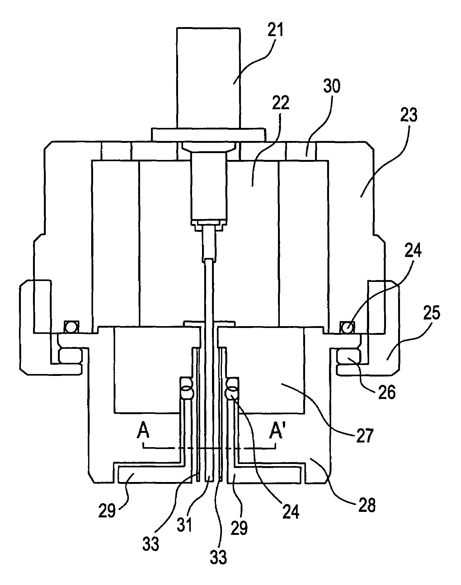
[0087]A piezoelectric element 121 interposed between a pair of ...

second embodiment

[0099]In this embodiment, ultrasonic vibrations are given to the object 113 by a method different from that of the first embodiment. FIG. 4 is a diagram showing a structure of a plasma CVD apparatus in accordance with another embodiment of the present invention. It is to be noted that the same portion or a portion having the same function is denoted by the same reference numeral in different drawings each illustrating an embodiment mode, and description thereof will not be repeated. As is apparent from FIG. 4, the electrode 112 is vibrated by an ultrasonic vibrator 141 so that the object 113 is ultrasonic-vibrated. Further, with such a structure, the interval between the pair of electrodes 112 and 114 can be set to 10 mm or less to thereby realize high-speed film formation.

third embodiment

[0100]FIG. 5 is a diagram showing a structure of a plasma CVD apparatus for forming a hard carbon coating on a tape-shaped material such as a magnetic tape. The plasma CVD apparatus shown in FIG. 5 includes a vacuum vessel 111, a roll-shaped electrode 155, an electrode 156 paired with the electrode 155, guide rollers 153 and 154 which also act as ultrasonic vibrators, a take-out drum 151 or 152, and a wind-up drum 152 or 151. Although not shown, a gas introducing system and a gas exhausting system for reactive gas, doping gas as well as dilution gas or the like are also provided in the apparatus.

[0101]As the tape-shaped object, a band-shaped object formed of a polyimide film is used. The band-shaped film object 157 travels from one drum 151 or 152 to the other drum 152 or 151 while it is taken up. The drum-shaped electrode 155 is connected to a high-frequency power supply 115 of 13.56 MHz so that discharge is generated between the electrode 155 and the electrode 156 which is a groun...


PUM

PropertyMeasurementUnit
pressureaaaaaaaaaa
frequencyaaaaaaaaaa
pressureaaaaaaaaaa

Abstract

In an apparatus for fabricating a carbon coating, an object such as a magnetic recording medium is disposed on a side of an electrode connected to a high-frequency power supply. Ultrasonic vibrations are supplied to the object. Discharge is generated between the electrode connected to the high-frequency power supply and a grounded electrode to fabricate a carbon coating on the surface of the object. Also, an electrode interval is set to 6 mm or less, pressure between the electrodes is set to 15 Torr to 100 Torr, whereby high-density plasma is generated to form an ion sheath on an anode side. Therefore, a coating is fabricated on the surface of the object by bombardment of ions.

Description

BACKGROUND OF THE INVENTION[0001]1. Field of the Invention[0002]The present invention relates to an apparatus for fabricating a hard carbon coating to be prepared as a surface protective film for a magnetic tape, an optical magnetic disc or the like, and a method of manufacturing such a hard carbon coating. Further, the present invention relates to an apparatus for manufacturing a magnetic disc medium having high durability and high recording density and excellent in productivity on a polymeric substrate material, and more particularly to an apparatus for manufacturing a protective film having functions of wear resistance and lubricating ability, which is industrially applied to an image equipment, an information equipment field and the like.[0003]2. Description of the Related Art[0004]Hitherto, there has been known a technique by which a diamond-shaped carbon coating is formed. The diamond-shaped carbon coating has a diamond structure and is also called a diamond-like carbon (DLC) ...

Claims


Application Information

Patent Timeline
Patent Type & Authority Patents(United States)
IPC IPC(8): B05D1/08C23C16/00C23C16/26H05H1/02H05H1/26C23C16/509G11B5/72G11B5/74G11B5/78G11B5/82G11B5/84G11B7/24G11B11/105
CPCC23C16/26C23C16/5096G11B5/72G11B5/74G11B5/78G11B5/8408G11B11/10584G11B11/10586G11B5/82Y10S430/146G11B7/24056G11B11/10582G11B5/727
Inventor YAMAZAKI, SHUNPEIITOH, KENJIHAYASHI, SHIGENORI
Owner SEMICON ENERGY LAB CO LTD
Why Eureka
Try Eureka