
Infra-red reflecting layered structure

a layered structure and infra-red technology, applied in the field of infrared reflecting layered structure, can solve the problems of low durability, low stability of silver layer, and negative influence of number and thickness of metal layer on visual light transmittance, etc., to achieve low solar heat gain coefficient, good visual light transmittance, and high stability

Active Publication Date: 2010-05-04
SAINT GOBAIN PERFORMANCE PLASTICS CHAINEUX
View PDF20 Cites 52 Cited by
  • Summary
  • Abstract
  • Description
  • Claims
  • Application Information

AI Technical Summary

Benefits of technology

[0011]It is also an object to provide an infra-red reflecting layered structure characterised by a good visual light transmittance and a low solar heat gain coefficient with a minimum number of metal layers.
[0051]According to further aspects a method of reducing the number of silver containing layers in an infra-red reflecting layered structure and a method of improving the visual light transmittance of an infra-red reflecting layered structure are provided.

Problems solved by technology

However, the number and the thickness of the metal layers have a negative influence on the visual light transmittance and on the cost and complexity of the manufacturing process.
However, a silver layer has a low stability, low durability and poor moisture and weather resistance.

Method used


Image

  • Infra-red reflecting layered structure
  • Infra-red reflecting layered structure
  • Infra-red reflecting layered structure

Examples


Embodiment Construction

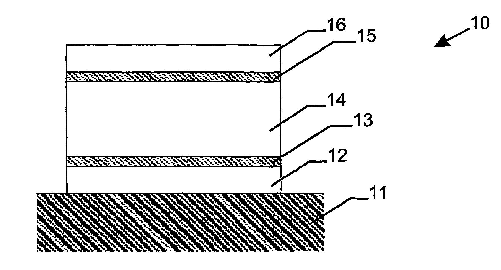
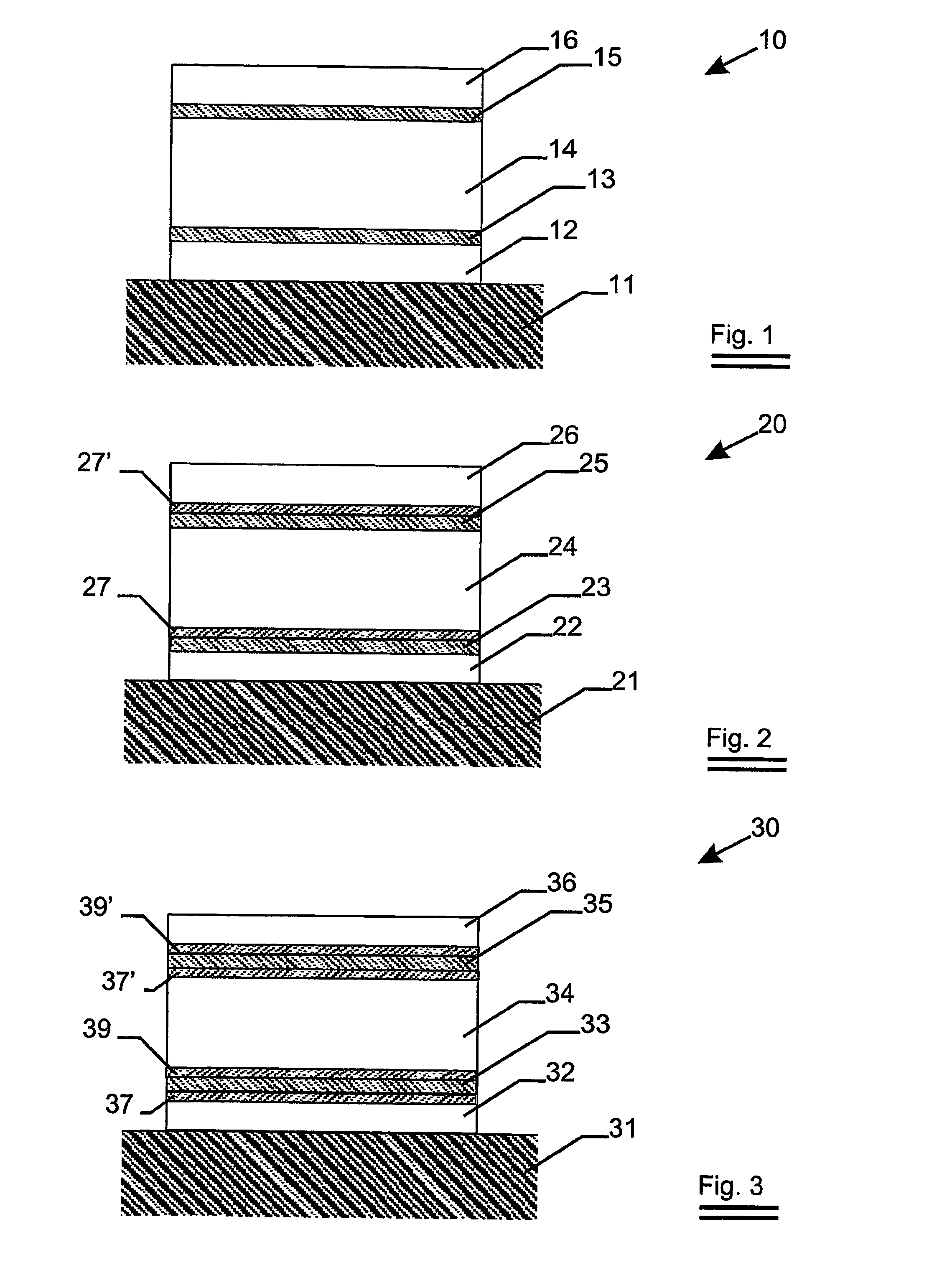
[0060]An embodiment of an infra-red reflecting layered structure 10 is shown in FIG. 1. The layered structure comprises three metal oxide layers 12, 14, 16 and two silver containing layers 13,15.

[0061]The metal oxide layers comprise TiO2.

[0062]The TiO2 is obtained by DC magnetron sputtering using rotatable ceramic TiOx targets with x between 1.5 and 1.7. These targets have enough electrical conductivity to be used as cathodes in a DC magnetron sputtering process.

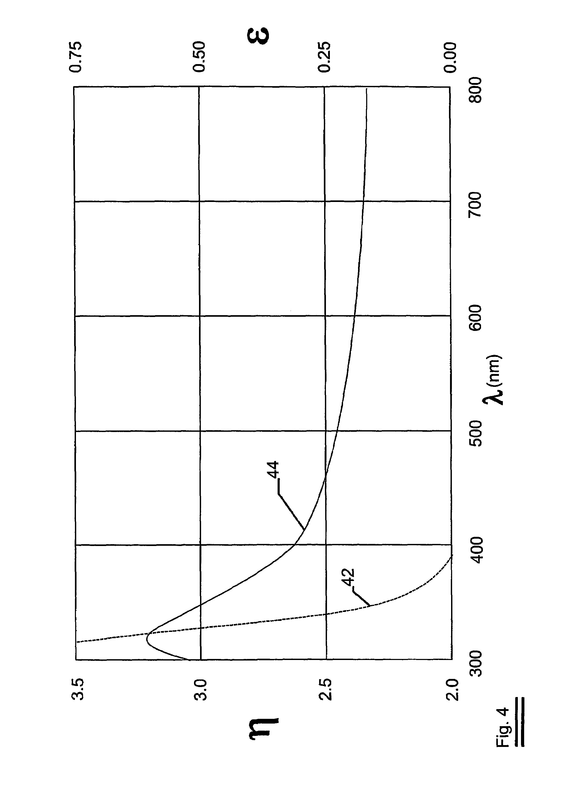
[0063]In FIG. 4, the refractive index (η) and the extinction coefficient (∈) of a TiO2 coatings can be seen. The refractive index (η) in function of the wavelength is given by line 44; the extinction coefficient (∈) of In function of the wavelength is given by line 42.

[0064]For wavelengths higher than 395 nm, the coating is absorption free. The refractive index at 510 nm is 2.41, which corresponds to the rutile phase of TiO2.

[0065]The silver containing layers 12, 14 comprise pure silver (i.e. silver with unavoidable impuriti...


PUM

PropertyMeasurementUnit
light transmittanceaaaaaaaaaa
SHGCaaaaaaaaaa
refractive indexaaaaaaaaaa

Abstract

The invention relates to an infra-red reflecting layered structure comprising a transparent substrate layer; a first metal oxide layer; a first silver containing layer, a second metal oxide layer; a second silver containing layer and a third metal oxide layer. The first, second and third metal oxide layer have a refractive index of at least 2.40 at a wavelength of 500 nm. The layered structure according to the present invention laminated on glass has a visual light transmittance (VLT) higher than 70% and a solar heat gain coefficient (SHGC) lower than 0.44. The invention further relates to the use of a layered structure as a transparent heat-mirror.

Description

FIELD OF THE INVENTION[0001]The invention relates to an infra-red reflecting layered structure and to the use of such a layered structure as heat-mirror.BACKGROUND OF THE INVENTION[0002]Heat-mirrors that reflect radiation in the infrared spectrum while transmitting radiation in the visible spectrum have important applications for example as windows in buildings or vehicles.[0003]For transparent heat-mirrors, visual light transmittance must be high, and hence the reflectivity and absorptivity must be low.[0004]In the United States of America for example, automotive windshields must have a transmittance of visible light of at least 70%.[0005]In the infrared, however, the heat-mirror must have high reflectivity and so transmittance and absorptivity in the infra-red must be low.[0006]Heat-mirrors comprising a stack of alternating dielectric and metal layers are known in the art.[0007]To obtain a heat-mirror characterised by a low heat transmittance, generally at least three metal layers...

Claims


Application Information

Patent Timeline
Patent Type & Authority Patents(United States)
IPC IPC(8): B32B17/06B32B17/10B32B27/36C03C17/245C03C17/36E06B9/24G02B5/20G02B5/28
CPCB32B17/10018H05K9/0096B32B17/10174B32B17/10761B32B27/36C03C17/2456C03C17/36C03C17/3613C03C17/3618C03C17/3639C03C17/3642C03C17/3644C03C17/3649C03C17/3652C03C17/3676E06B9/24G02B5/208G02B5/282B32B17/10036C03C2217/212C03C2217/255C03C2217/256C03C2217/93C03C2218/152C03C2218/155H01J2211/446B32B27/308B32B2311/04B32B27/365B32B27/40B32B2307/212B32B2333/08B32B2551/00B32B2457/204B32B2367/00B32B2369/00B32B2375/00B32B15/04B32B15/08B32B7/12
Inventor PERSOONE, PETERVLAEMINCK, KOENLIEVENS, HUGO
Owner SAINT GOBAIN PERFORMANCE PLASTICS CHAINEUX
Learn More