
Apparatus for producing nuclear spin-polarized noble gas, nuclear magnetic resonance spectrometer, and nuclear magnetic resonance imager

a technology of spin-polarized noble gas and nuclear magnetic resonance, which is applied in the field of apparatus for producing nuclear spin-polarized noble gas, nuclear magnetic resonance spectrometer, and nuclear magnetic resonance imager, can solve the problems of undesirable spin relaxation and decrease in nmr signal intensity, and achieve the effect of reducing nmr signal intensity

Inactive Publication Date: 2010-05-04
NAT INST OF ADVANCED IND SCI & TECH
View PDF9 Cites 13 Cited by
  • Summary
  • Abstract
  • Description
  • Claims
  • Application Information

AI Technical Summary

Benefits of technology

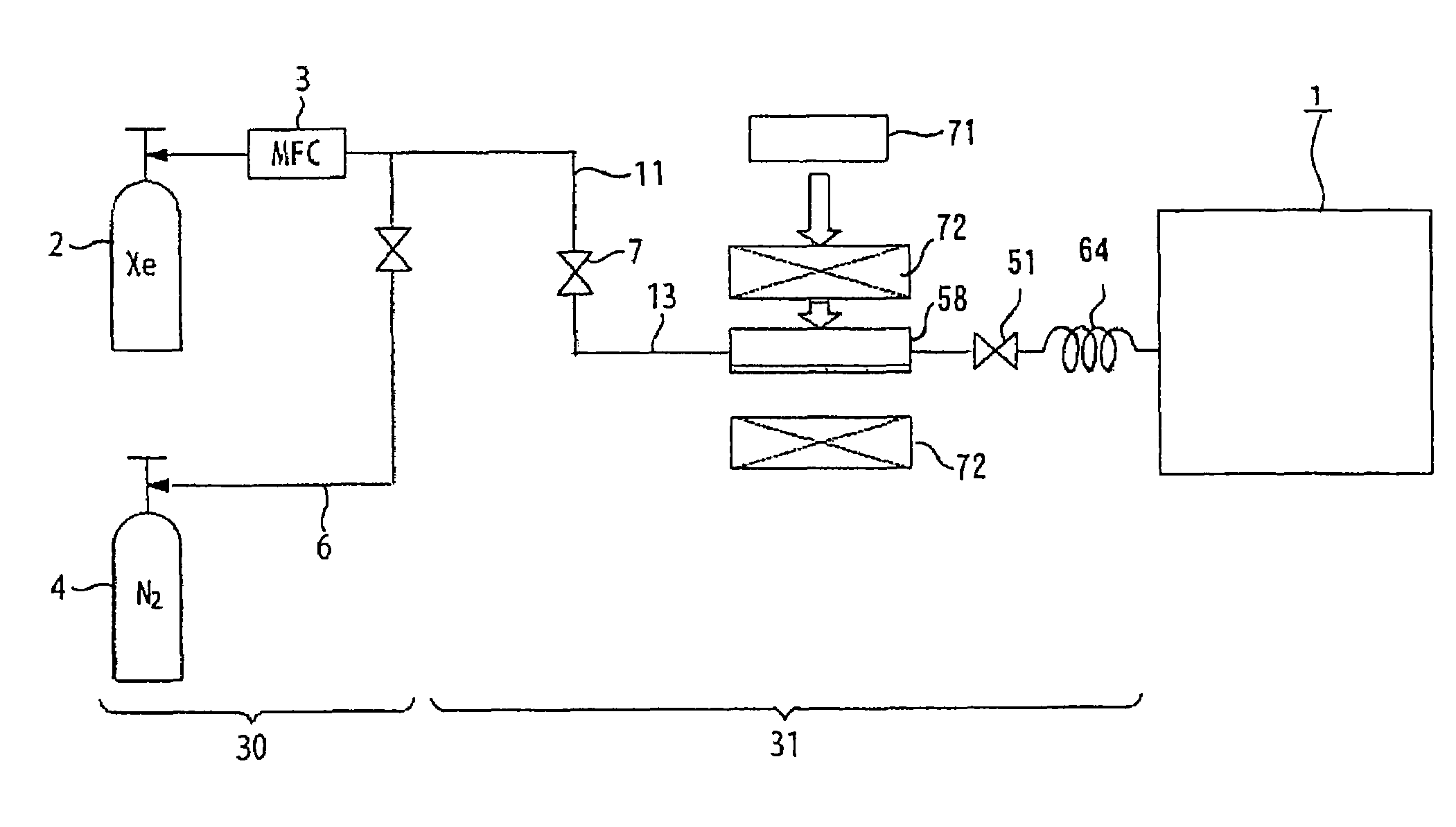
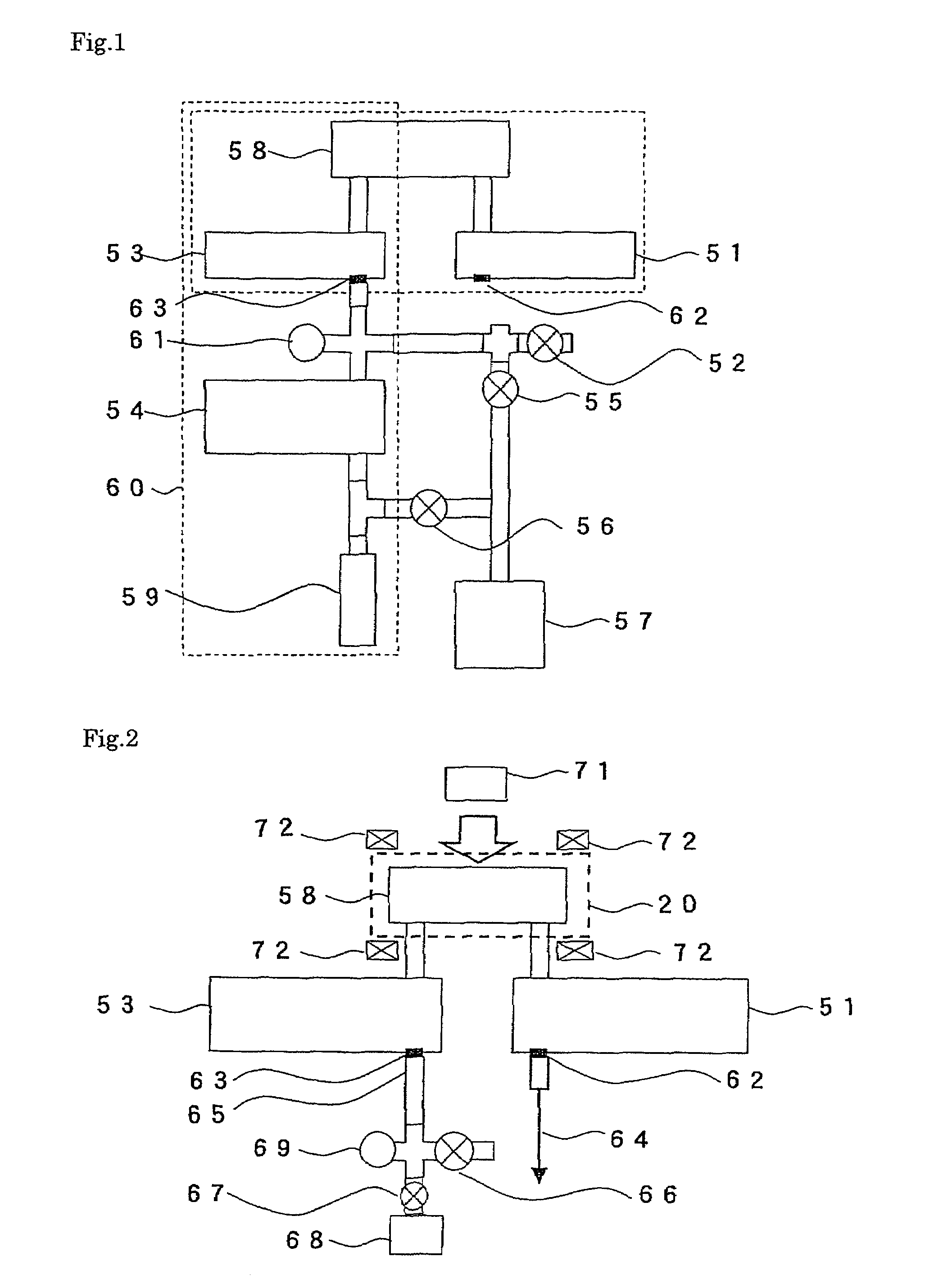
The present invention provides an apparatus for producing a nuclear spin-polarized noble gas that can prevent the decrease in NMR signal intensity caused by spin relaxation. The apparatus includes a cell with a reaction chamber, a gas introduction conduit, a gas discharge conduit, a system for applying a magnetic field, a system for delivering laser light, and a capillary tube. The apparatus can produce a high-quality nuclear spin-polarized noble gas with high efficiency and can be easily assembled, maintained, and used in a nuclear magnetic resonance spectrometer or imaging device. The invention also provides a nuclear magnetic resonance spectrometer and imaging device that use the produced nuclear spin-polarized noble gas.

Problems solved by technology

The phenomenon in which the difference in the number of occupied spin of a nuclear spin-polarized noble gas decreases and becomes close to the Boltzmann distribution is called “spin relaxation.” The spin relaxation is undesirable because when it occurs, the NMR signal intensity decreases.

Method used


Image

  • Apparatus for producing nuclear spin-polarized noble gas, nuclear magnetic resonance spectrometer, and nuclear magnetic resonance imager
  • Apparatus for producing nuclear spin-polarized noble gas, nuclear magnetic resonance spectrometer, and nuclear magnetic resonance imager
  • Apparatus for producing nuclear spin-polarized noble gas, nuclear magnetic resonance spectrometer, and nuclear magnetic resonance imager

Examples


example 1

[0086]Using extra fine capillary tubes made of fused silica and having an inside diameter of 0.53 mm and a length of 2 m (fused silica capillary tubes manufactured by GL Science, Ltd.), the NMR signal intensity was measured at nuclear spin polarized xenon gas flow rates of 5, 10, 15, 20, 25 and 30 sccm.

[0087]A cell as described before was used. Xenon gas (manufactured by Taiyo Nippon Sanso Corporation, purity: 99.995%) was introduced into the cell 58, and irradiated with light having a wavelength of 794.7 nm, a half width 0.5 nm, and an output of 27 W using laser diodes (manufactured by PD-LD Inc.). A magnetic field with an intensity of 1.25×10⁻² T was applied to the cell 58 using two ring-shaped permanent magnets (manufactured by Magna Co., Ltd.). The temperature of the cell 58 was set at 200° C.

[0088]The intensities of the NMR signals were measured using a pulsed NMR spectrometer (manufactured by Thamway Co., Ltd.). The measurement conditions were a magnetic field intensity of 0.3...


PUM


Abstract

An apparatus for producing a nuclear spin-polarized noble gas by spin-polarizing a noble gas in the presence of an optical pumping catalyst under application of magnetic field and laser light, including a cell having a thin reaction chamber, a gas introduction conduit connected in fluid communication with the reaction chamber for feeding the noble gas, a gas discharge conduit connected in fluid communication with the reaction chamber, a first gate valve having an outlet port connected to the gas introduction conduit and an inlet port adapted to be in fluid communication with a noble gas introduction line, a second gate valve having an inlet port connected to the gas discharge conduit and an outlet port, and a capillary tube removably connected to the outlet port of the second valve for recovering a nuclear spin-polarized noble gas produced in the reaction chamber. The apparatus may be directly connected to NMR or MRI.

Description

CROSS-REFERENCE TO RELATED APPLICATION[0001]This application claims, under 35 USC 119, priority of Japanese Patent Application No. 2006-316485, filed Nov. 24, 2006, disclosures of which, inclusive of the specification, claims and drawings, are hereby incorporated by reference herein.BACKGROUND OF THE INVENTIONField of the Invention[0002]The present invention relates to an apparatus for producing a nuclear spin-polarized noble gas, and to a nuclear magnetic resonance spectrometer and a nuclear magnetic resonance imager connected to the apparatus for using a nuclear spin-polarized noble gas produced therein.[0003]Gases at atmospheric pressure, which have a lower atomic density than liquids and solids, had not been used until recently as targets in nuclear magnetic resonance spectroscopy (NMR) or magnetic resonance imaging (MRI).[0004]However, when a noble gas composed of monatomic molecules having a nuclear spin with a spin quantum number of ½ such as the xenon isotope having a mass n...

Claims


Application Information

Patent Timeline
Patent Type & Authority Patents(United States)
IPC IPC(8): G01V3/00
CPCG01R33/282H05H3/00G21K1/16
Inventor HATTORI, MINEYUKIHIRAGA, TAKASHIYAMAMOTO, NORITAKA
Owner NAT INST OF ADVANCED IND SCI & TECH
Learn More