Method and system for removal of ammonia from wastewater by electrolysis

a technology of ammonia removal and wastewater, applied in the field of wastewater and process water treatment, can solve problems such as algae and plant growth, and achieve the effect of reducing the ammonia level reaching the environmen

Inactive Publication Date: 2010-06-15
SPIELMAN RICK B +1
View PDF8 Cites 11 Cited by
  • Summary
  • Abstract
  • Description
  • Claims
  • Application Information

AI Technical Summary

Benefits of technology

[0014]The configuration described has a number of advantages. The ammonia is removed from the system with the application of electrical energy. There are no waste products. The ammonia that is removed from the wastewater can be recovered using standard refrigeration techniques and can result in a valuable byproduct fertilizer. Unlike biological solutions, our invention does not rely on living organisms for the success of the process. The...

Problems solved by technology

While major reductions in solids can be expected using these conventional processes, there is little reduction in nitrogen containing compounds, particu...

Method used


Image

  • Method and system for removal of ammonia from wastewater by electrolysis
  • Method and system for removal of ammonia from wastewater by electrolysis
  • Method and system for removal of ammonia from wastewater by electrolysis

Examples


first embodiment

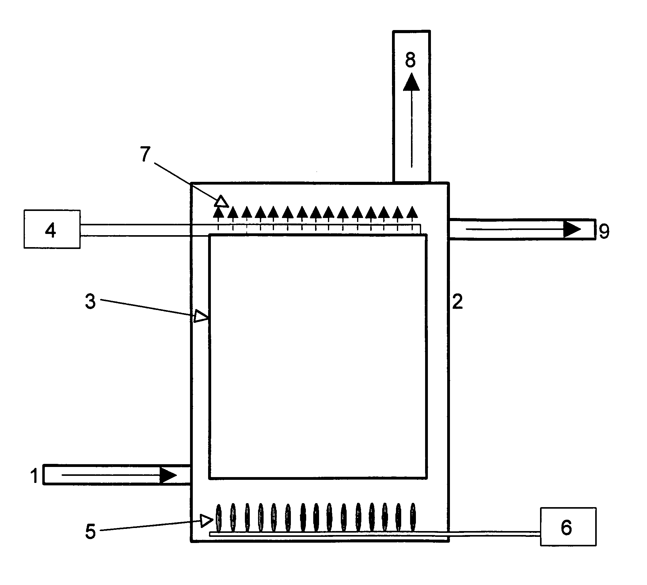
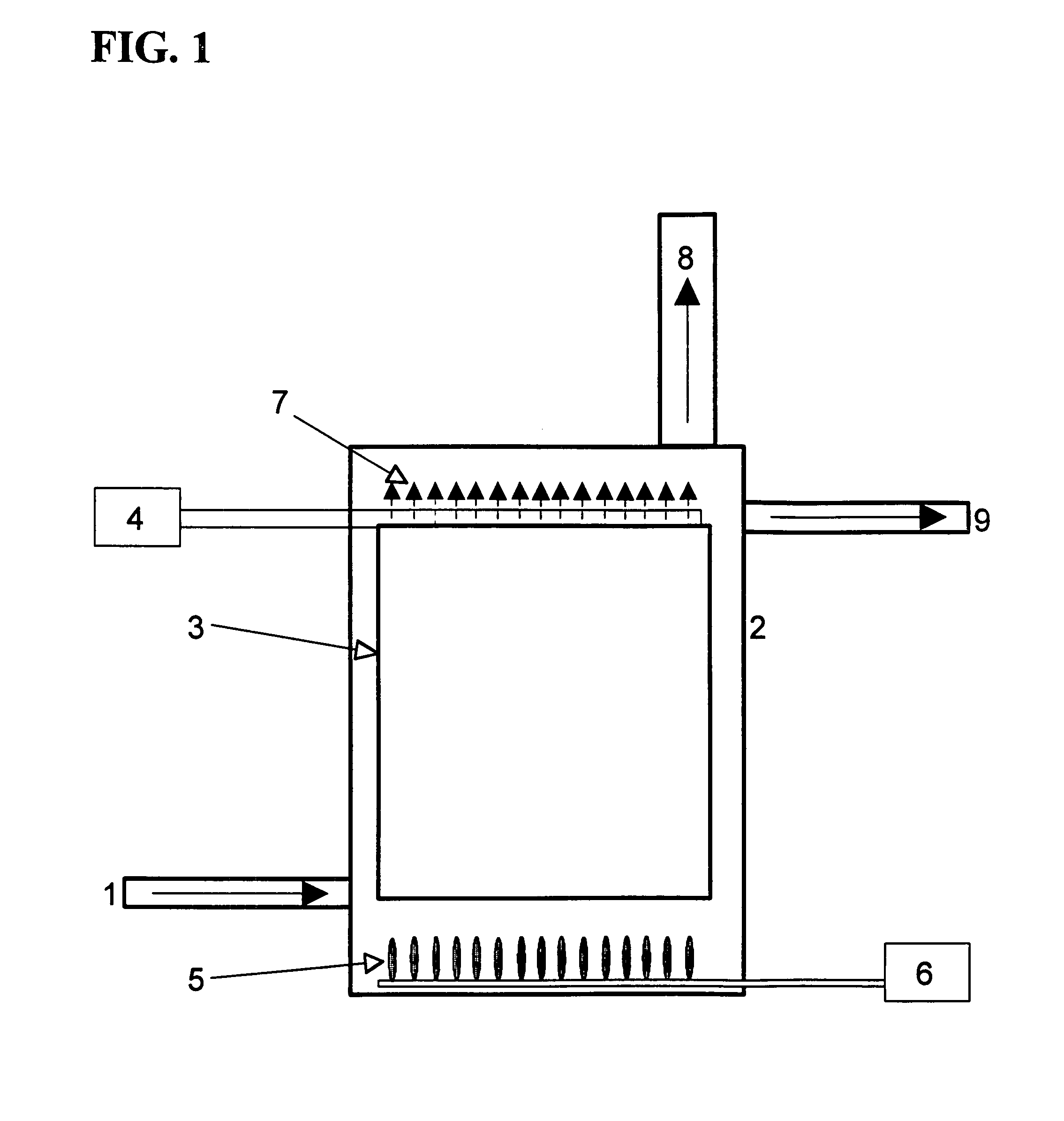
[0025]In operation, electrical current flows uniformly through the water between the plates. This current heats the water and is a parasitic loss and has no beneficial action. It is therefore advantageous to operate with the electrode spacing as small as is mechanically possible. The spacing is typically limited by the flatness of the electrodes, particle content of the wastewater, and the operational safety margin desired for the system. The first embodiment uses, but is not limited to, a spacing of 3 millimeters (3 mm). Smaller electrode spacings permit lower operational voltages for the system. Voltage regulation provides no added performance to the system. During electrolytic cell operation, the pH of the water near the cathode increases to level>9. At or above a pH of 9, aqueous ammonium (NH4) is converted to gaseous ammonia (NH3).

[0026]Wastewater flows through the space between the plates. In this embodiment the water flows from the bottom of the electrodes to the top. Other w...

second embodiment

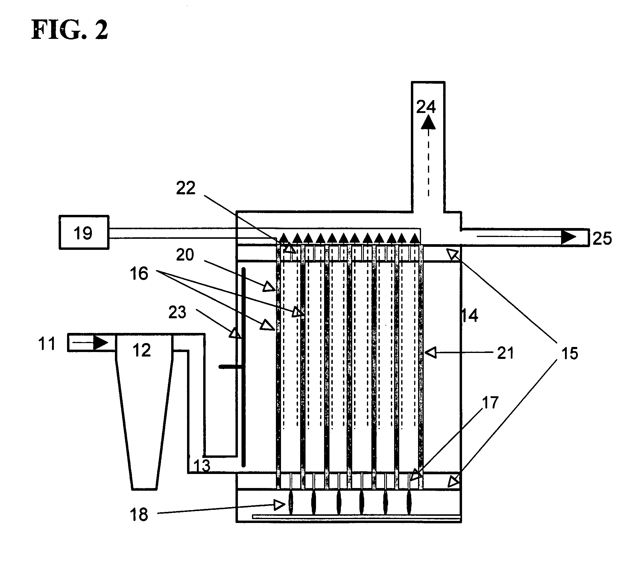
[0029]the system consists of one or more pairs of porous electrodes arranged in a substantially planar fashion. The effectiveness of this or other embodiments is not impacted by the use of other geometries such as cylindrical geometries. The porosity of the electrodes is needed in order to maintain a flow of wastewater through the cell. The electrodes are fabricated from corrosion resistant materials such as but not limited to titanium. Other coatings may be placed on the titanium. These coatings may consist of, but are not limited to, thin layers of such oxides as rhenium oxide, zirconium oxide, and rhodium oxide.

[0030]The embodiment uses, but is not limited to, electrodes whose width is 30 cm and whose length is 100 cm. This results in an electrode area of ˜3000 cm2. Electrode dimensions can range from a few cm to hundreds of cm and are limited only by the physical constraints of the application and the engineering required to hold the electrode spacing to adequate tolerances.

[003...


PUM


Abstract

A method and system are described to treat ammonia-containing wastewater or process waters. Sewage containing human or animal waste and certain process liquids, typically water, contains high levels of nitrogen in the form of ammonia. An electro-chemical method to extract the ammonia from the wastewater is also described. The system described is one implementation of this method. One or more electrolysis cells convert ammonium to ammonia where the generated ammonia gas can readily be extracted for disposal or reuse. Such a system can involve electrolysis cells of numerous types as described herein.

Description

[0001]This application claims the benefit of U.S. Provisional Application No. 60 / 788,714 filed Apr. 4, 2006, which is hereby incorporated by reference in its entirety.TECHNICAL FIELD OF THE INVENTION[0002]The present invention relates generally to the field of treatment of wastewater and process water, more specifically, to the reduction in the level of ammonia and organic ammonia compounds in wastewater and process water, regardless of source.BACKGROUND OF THE INVENTION[0003]Human and animal waste is the primary source of nitrogen in most wastewater discharges. In addition, certain process waters, including but not limited to industrial process waters, contain significant amounts of nitrogen compounds. Wastewater containing nitrogen compounds such as ammonia; organic nitrogen, nitrates, and nitrites that contaminate ground and surface water resources are a major concern in a world facing potable water shortages. Traditional wastewater systems do little or nothing to reduce the leve...

Claims


Application Information

Patent Timeline
IPC IPC(8): B01D59/00
CPCC02F1/4618C02F1/001C02F1/36C02F2001/46119C02F2001/46152C02F2201/4619C02F2001/4619C02F2101/16C02F2201/46115C02F2201/4617C02F2001/46161
Inventor SPIELMAN, RICK B.SUMMERS, LINK E.
Owner SPIELMAN RICK B
Why Eureka
Try Eureka