
Integrated apparatus and methods for treating liquids

a micro-device and liquid technology, applied in the direction of machines/engines, sedimentation separation, feed/discharge of settling tanks, etc., can solve the problems of limited application of microfluidic research specifically to the needs of clinical chemistry, high surface area to volume ratio, and little engineering design and development strategy to allow integrated or modular “on-chip” sample manipulation, etc., to achieve finely controlled geometrical and flow conditions

Inactive Publication Date: 2010-06-29
CROWLEY TIMOTHY PHD +1
View PDF20 Cites 13 Cited by
  • Summary
  • Abstract
  • Description
  • Claims
  • Application Information

AI Technical Summary

Benefits of technology

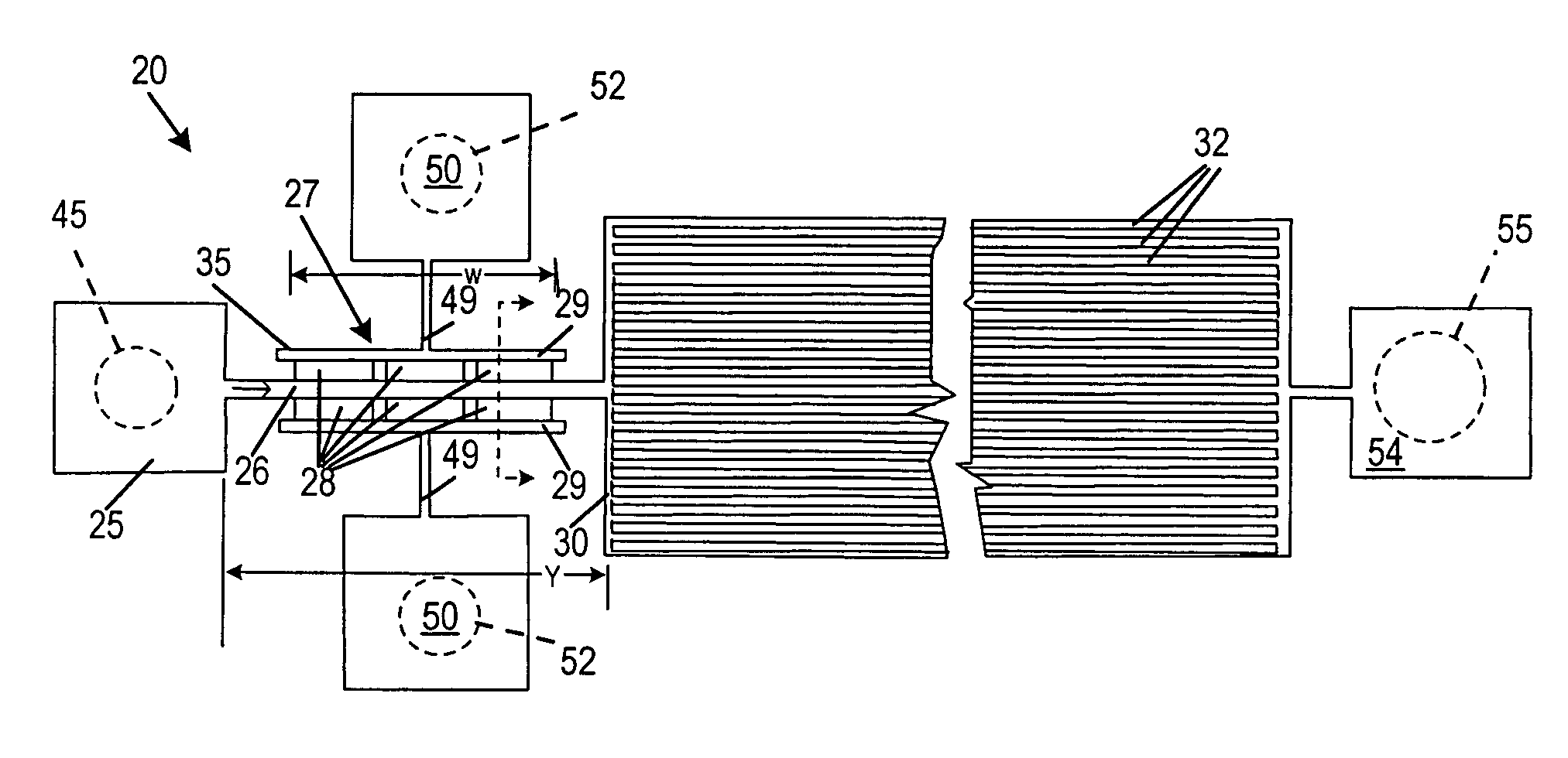
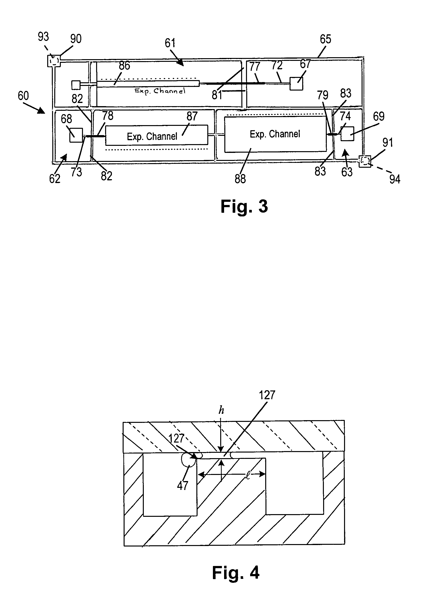
[0015]In a preferred embodiment, a flow channel in which the liquid specimen moves by capillary action from an input reservoir leads to an expanded channel. There, parallel liquid paths connected to the flow channel sustain the presence of the motivating force and thus duration of capillary action moving the liquid in the flow channel. This extends the device operating time. A comparable in length flow channel without the expansions described here is estimated to be able to operate for about 15 seconds, whereas with this expanded channel here described operation times up to two minutes are possible. Filters opening from the flow channel direct liquid of desired specimen subfractions filtered from a specimen to a collection region. Again capillary action is the motivating force. The arrangement is particularly useful in the fractionation of a complex fluid suspension such as blood, where suspended matter such as macromolecules and formed elements (e.g. red and other blood cells) are moved along the liquid flow channel and while a desired subfraction of filtrate such as plasma exits via the filter constructs into the collection region. Plasma production is in the nanoliter range compared to the picoliter of the prior art “straight channel” device.
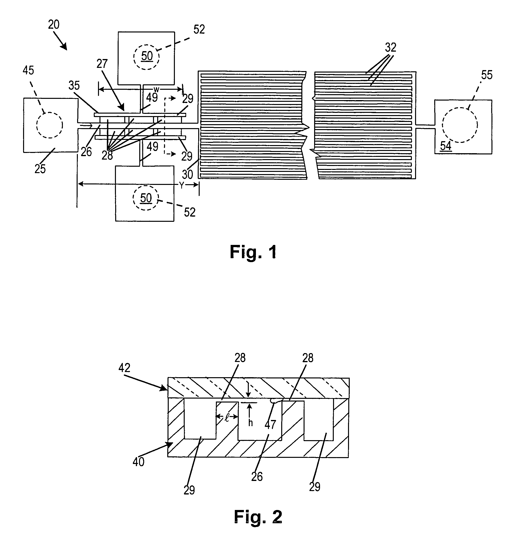
[0020]In another exemplary embodiment of the invention, controlled lysis of cells in a suspension such as red blood cells in liquid whole blood is accomplished. Again, filter openings or pores communicate through the sides of a liquid flow channel along which the suspension moves by capillary action. The size of the pores and the length of a passage from the pore that draws liquid to a collection site are chosen to provide controlled levels of cell stress and duration and thus control the level or prevention of lysis of cells that adhere to and are deformed by the filter opening. The factors that affect lysing are stress on the cell and the duration of such stress. In the case of fractionation of a suspension such as whole blood, where only liquid such as plasma is desired as the filtrate, then the filtrate flow channel away from the filter to the filtrate collection site is made sufficiently short as to shorten the time of residence of a cell at the filter pore particularly during the initial wetting period when capillary pressure across the filter pore or pores is greatest. On the other hand, if a greater or lesser degree of lysis is desired, then, a longer channel is used.

Problems solved by technology

Although much progress has been made in developing the diagnostics capability of μTAS, to date, little has been done in the way of engineering design and development strategies to allow integrated or modular “on-chip” sample manipulation, preparation and pretreatment for complex biological fluids, such as blood and the like.
These include high surface area to volume ratios, and rapid transport processes due to small transfer distances.
These complex fluids typically require sample preparation to fractionate various fluid components that either interfere with chemical analysis, or provide fluid sub-fractions containing desired analytes.
To date, microfluidic research applied specifically towards the needs of clinical chemistry has been limited.

Method used


Image

  • Integrated apparatus and methods for treating liquids
  • Integrated apparatus and methods for treating liquids
  • Integrated apparatus and methods for treating liquids

Examples


Embodiment Construction

Microfilter

[0061]As illustrated in FIGS. 1 and 2, a microfiltering system 20 is fabricated in silicon and glass. This is done using methods similar to those used in integrated circuit fabrication as described below. The microfilter 20 has an input reservoir 25, a narrow filtration channel 26 containing a pair of transverse flow microfilters 27, a pair of plasma outlet channels 29 to collect filtrate. A downstream expanded channel 30 connects in series with the filtration channel 26. In one exemplary embodiment, the expanded channel 30 of the device contains an array of parallel, ˜45 μm wide, and 15 mm long flow channels 32, as shown in FIG. 1.

[0062]The microfilter 27 is a weir type filter fabricated as a series of rectangular openings 28, the ‘filter pores’, located on both sides of the 100 μm wide filtration channel 26. In one preferred exemplary embodiment, used for the fractionation of nanoliter amounts of whole blood, the dimensions of each filter pore was a width ‘w’ 200 μm wid...


PUM

PropertyMeasurementUnit
lengthaaaaaaaaaa
lengthaaaaaaaaaa
lengthaaaaaaaaaa

Abstract

A passive self energized, liquid device operates entirely on capillary action. A microfilter fractionates nanoliter volumes of suspension such as whole blood into suspended particles or cells and liquid fractions. Blood, for example, is fractionated with minimal cell lysis, and the filtrate (plasma) flux is dependent upon design parameters similar to factors controlling blood filtration in microporous membranes, i.e. active filter area, fluid velocity and microfilter geometry. Weir-style filters communicate with a blood flow channel to separate plasma from blood moving by capillary action. An expanded downstream channel with multiple parallel capillary blood flow path provides continuing movement of blood past the filters. Lysing is controlled by the size of the filter pores and the duration of adherence of the red blood cells to the pores. The controlled lysis or prevention of lysis of red blood cells is accomplished by manipulating the significant capillary forces generated in the filters. Filtration, cell lysis and microchannel blood flow models are integrated into an overall microfilter design useful for fabricating microfilter devices for lab-on-a-chip clinical applications where they can be coupled with on-chip electrical and electro-optical devices.

Description

CROSS REFERENCE TO RELATED APPLICATIONS[0001]This application claims priority from the provisional patent application Ser. No. 60 / 408,677 filed Sep. 7, 2002 in the name of Vincent B. Pizziconi and Timothy Crowley entitled“Self-Energizing, Scalable and Integrative Hybrid Informatic Method and Apparatus to Manipulate, Process, Diagnose and Treat Complex Fluids” incorporated herein by reference.STATEMENT OF GOVERNMENT FUNDING[0002]Financial assistance for this project was provided by the U.S. Government through the National Science Foundation under Contract / Grant Number DB1 9602258. Therefore the United States Government may own certain rights to this invention.FIELD OF THE INVENTION[0003]This invention relates to microdevices and methods for treating, analyzing complex liquids and more particularly to devices of this kind formed on and integrated with semiconductor device supporting substrates.BACKGROUNDIntroduction[0004]The potential of miniature analytical systems in medicine and bi...

Claims


Application Information

Patent Timeline
Patent Type & Authority Patents(United States)
IPC IPC(8): B01D35/00G01N33/48B01D61/00B01D37/00B01D61/18B01D67/00B01D71/02B01L3/00B44C1/22G01N21/01G01N33/49H01L
CPCB01D61/18B01D67/0058B01D71/02B01L3/502753G01N33/49B01L2300/0816B01L2400/0406G01N21/01B01L2300/0681B01D71/0213
Inventor CROWLEY, TIMOTHYPIZZICONI, VINCENT B.
Owner CROWLEY TIMOTHY PHD
Learn More