Protection of reinforcement

a technology of steel reinforcement and reinforcement, applied in the direction of paper/cardboard containers, lamination, containers, etc., can solve the problems of affecting the health and safety of workers, affecting the protection effect of steel reinforcement, and affecting the protection effect of the activating agent, so as to achieve the effect of low health and safety risk

Inactive Publication Date: 2010-07-06
GLASS +1
View PDF21 Cites 18 Cited by
  • Summary
  • Abstract
  • Description
  • Claims
  • Application Information

AI Technical Summary

Benefits of technology

[0011]This invention allows the use in concrete of established solutions to the problems arising when sacrificial anodes are used in resistive environments, solutions involving the exposure of the anode to aggressive agents such as sulphate or halide ions that would otherwise cause reinforced concrete deterioration. Such solutions have a relatively low health and safety risk and allow the use of established parameters for anode efficiency when calculating anode output and anode life.

Problems solved by technology

The use of conventional sacrificial anode backfills developed for resistive soils is mired by the deleterious effects of some of the ionic components they contain on the reinforced concrete, the dimensional instability of the backfill in a range of moisture conditions and the need to contain the backfill and its active ingredients in the vicinity of the base metal.
In addition some of the components of other materials that may be used to maintain base metal activity in concrete may also induce damage to both the concrete and the steel reinforcement.
The inertness of the inorganic porous layer limits the removal of the activating agent from solution that would draw the activating agent away from the base metal.
This porous layer inhibits the movement of the activating agent away from the base metal but it does not stop the flow of ionic current between the base metal and the protected steel.

Method used


Image

  • Protection of reinforcement
  • Protection of reinforcement
  • Protection of reinforcement

Examples


example 1

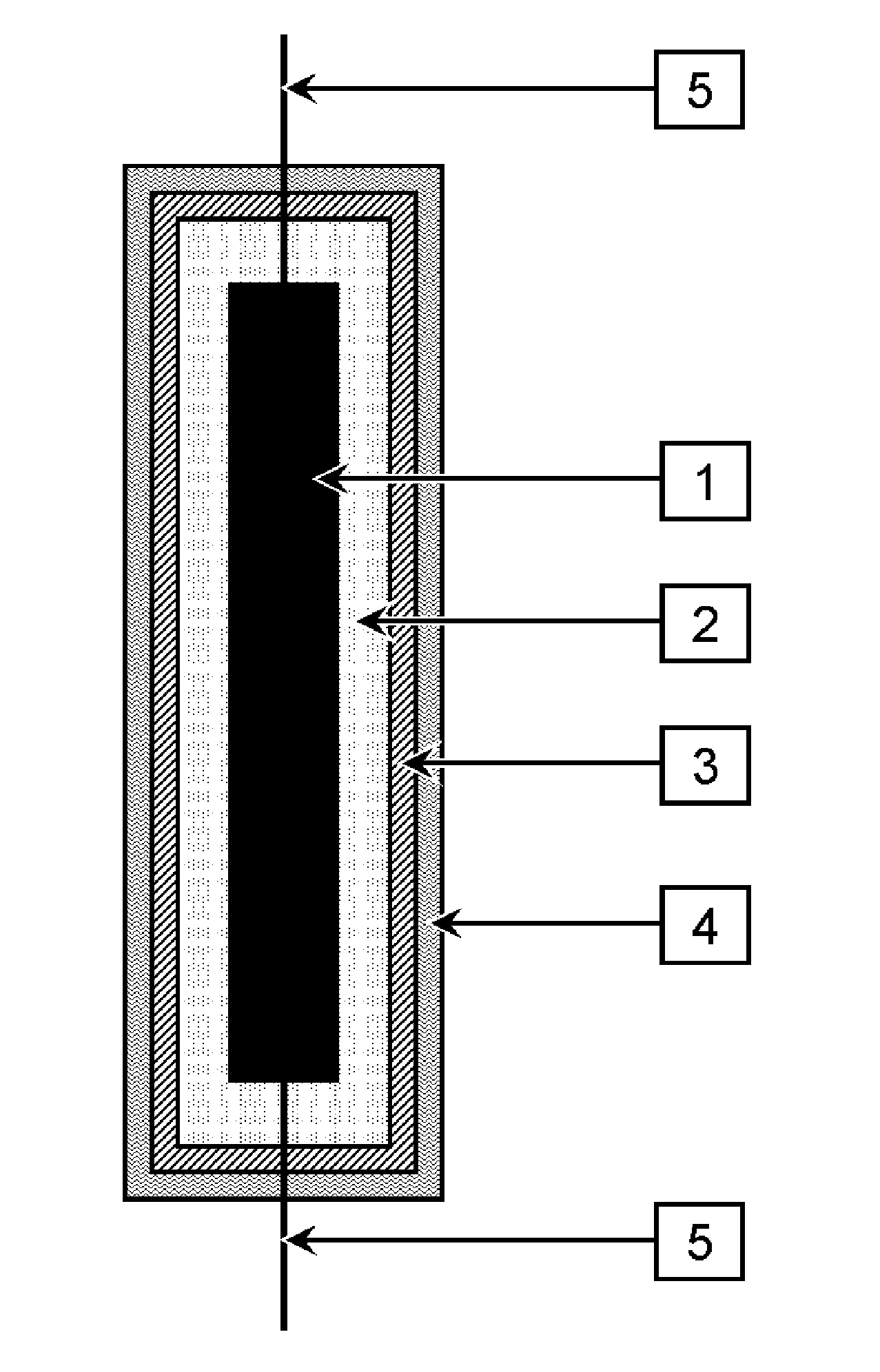
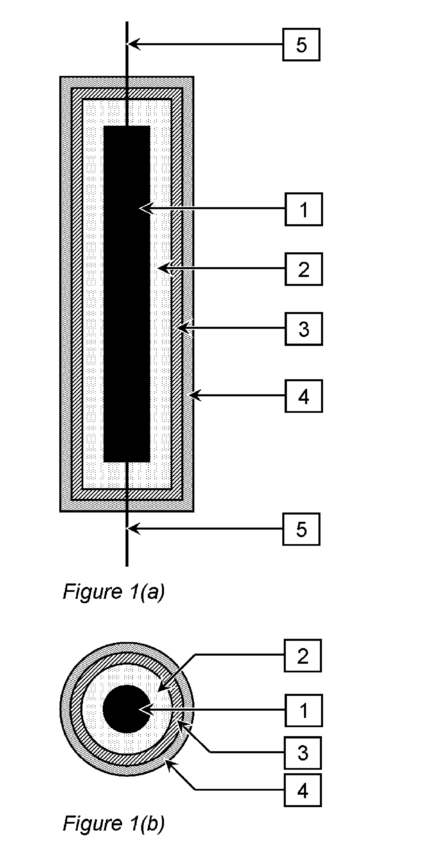
[0050]A sacrificial anode assembly consisting of a base metal, electron conductor and gypsum containing free sulphate ions was produced and tested. The base metal consisted of a block of aluminium alloy measuring 29.7 mm by 11.9 mm by 8.6 mm. The alloy was US Navy specification MIL-A-24779(SH). An electron conductor consisting of a 1.0 mm2 sheathed copper core cable was connected to the aluminium alloy. This connection was made by drilling a 4 mm diameter hole to a depth of 8 mm into the 11.9 by 8.6 mm face of the block, stripping away 8 mm of sheath off the end of the copper core cable, inserting the exposed copper core into the drilled hole and securing it with a 3.5 mm diameter aluminium pop rivet in the drilled hole. The connection was insulated with a fast curing silicone sealant obtained from a builder's merchant. Once the sealant had cured, the aluminium block was suspended centrally in a cylindrical plastic mould made from a 50 mm length of 50 mm diameter plastic pipe with a...

example 2

[0060]An aluminium anode assembly with layers was produced and tested. The aluminium alloy was the same as that used in Example 1 and the dimensions of the block used were 11.8 mm by 5.2 mm by 27.0 mm. A sealed electrical connection was made on the 11.8 mm by 5.2 mm face of the block which was then located in a cylindrical plastic mould made from a 50 mm length of 50 mm diameter pipe that was filled with a fluid mixture of plaster, potassium sulphate and tap water as described in Example 1. The plaster was then allowed to cure to form a rigid gypsum material with free sulphate ions.

[0061]A Laponite clay (grade JS Laponite supplied by Rockwood Additives Ltd. in the UK ) was mixed with deionised water in the proportion 1 Laponite to 5 water by weight using a high shear mixer. The solution was mixed for 20 minutes and allowed to stand for a further 40 minutes before use. A 1 mm thick layer of the resulting mixture was brush applied to the surface of the gypsum and allowed to dry for se...

example 3

[0067]An aluminium anode assembly with layers was produced as described in Example 2. The dimensions of the aluminium block used were 12.5 mm by 7.7 mm by 20.1 mm and a sealed electrical connection was made on the 12.5 mm by 7.7 mm face of the block. The remaining assembly production detail is identical to that described in Example 2.

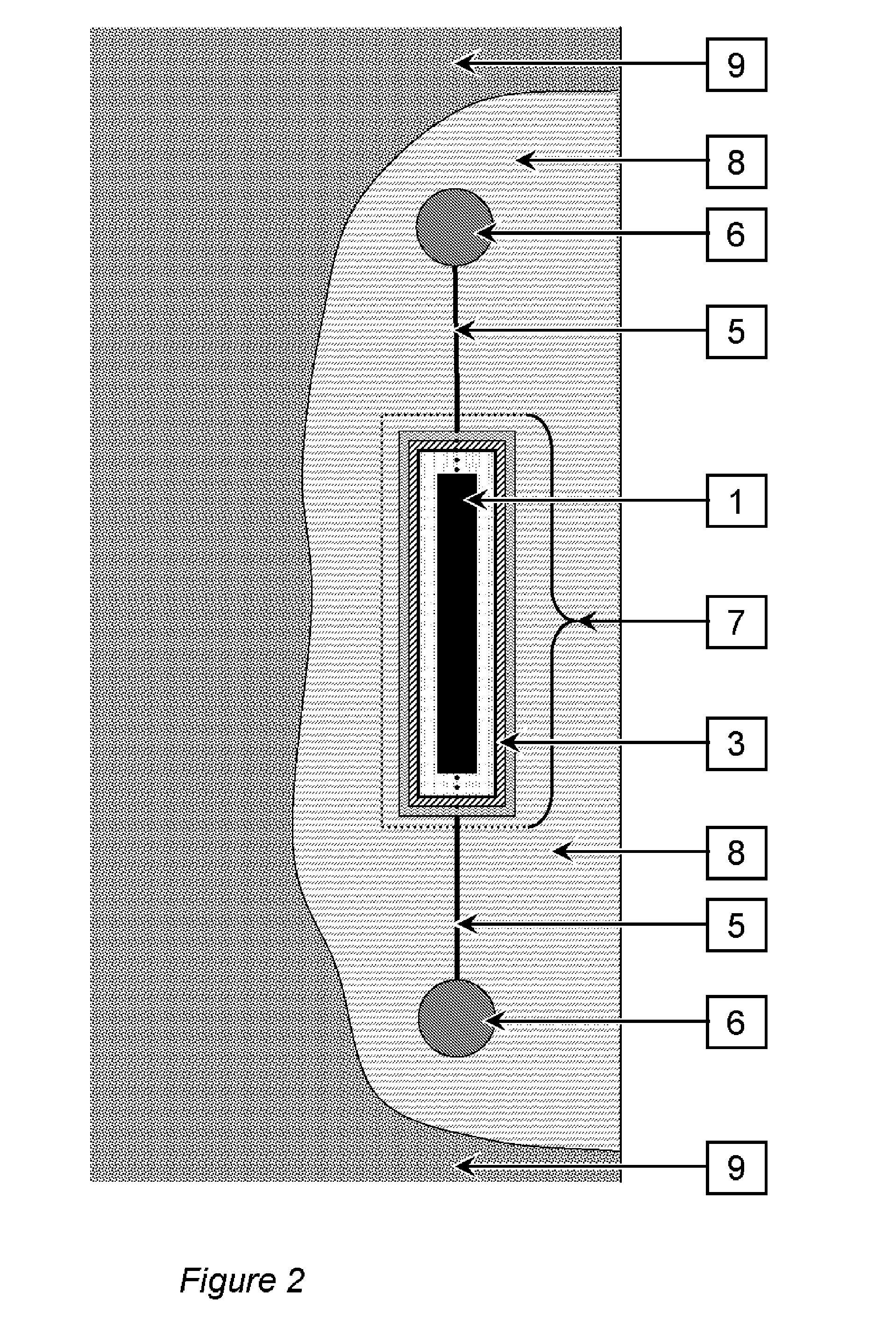
[0068]The experimental arrangement including the reinforced concrete specimen used to test the aluminium anode assembly is shown in FIG. 3 and described in Example 2. The concrete block into which the anode assembly was cast for testing purposes was removed from the mould after 24 hours. It was then cured standing in water for 68 days at an average temperature of 11° C. The anode was connected to the steel and the steel potential was held at −350 mV relative to the saturated copper sulphate reference electrode from the start of this period to the end of the test. After this period, the block was removed from the water and allowed to dry for a further 11...


PUM

PropertyMeasurementUnit
resistivityaaaaaaaaaa
current densityaaaaaaaaaa
lengthaaaaaaaaaa

Abstract

A method of protecting steel in concrete is disclosed. It consists of connecting the steel (6) to a discrete sacrificial anode assembly (7) comprising a base metal (1), a relatively small quantity of catalytic activating agent in contact with the base metal and a substantially inert porous layer (3) that surrounds the base metal and catalytic activating agent. The inert porous layer efficiently maintains a sustainable concentration gradient of the catalytic activating agent between the base metal and the surrounding environment as a result of the electric field across this layer. The preferred porous layer comprises a material that exhibits a net repulsion of negative ions from its pore system and the preferred catalytic activating agent comprises doubly charged sulphate ions as small electric fields maintain very high concentration gradients of these ions resulting in high concentrations at the base metal surface and insignificant concentrations at the assembly periphery.

Description

TECHNICAL FIELD[0001]This invention relates to the protection of steel reinforcement in concrete construction using sacrificial anodes and in particular to the activation and containment of components of the material used to maintain sacrificial anode current output in reinforced concrete.BACKGROUND ART[0002]Sacrificial cathodic protection is a technique that is used to control the corrosion of steel. It involves connecting to the steel a base metal or alloy that is less noble than steel, such as a metal or alloy of zinc, aluminium or magnesium. The base metal is consumed by anodic dissolution and in the process current flows to the steel which becomes the protected cathode of the base metal-steel couple.[0003]One application of sacrificial cathodic protection is to protect steel reinforcement in concrete. U.S. Pat. No. 6,022,469 describes the use of sacrificial anodes in the repair of corrosion damaged concrete structures. Sacrificial anode systems may be applied to a concrete surf...

Claims


Application Information

Patent Timeline
Patent Type & Authority Patents(United States)
IPC IPC(8): C23F13/16C23F13/06C23F13/08
CPCC23F13/16C23F2201/02Y10T29/53204Y10T29/532Y10T156/10C23F13/06C23F2213/22C23F13/00C23F13/08C23F13/12C23F13/14
Inventor GLASS, GARETHROBERTS, ADRIAN
Owner GLASS
Why Eureka
Try Eureka